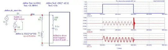
Here is a simulation where you can see what happens when you push a button in a "inductive" circuit. Equations can also be written ...
There is 3 phases in the behavior.
1- When you just push the "button" (here, it is a "clean" push ...).
The starting current (~ 9 A peak) can be somewhat higher then in steady state because of the switching transient. It is a function relative to the voltage "phase" at starting "push".
2- Steady state (current calculated as usual in "sinusoidal" circuits).
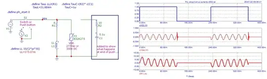
3- When button is released, energy in inductor (if not equal to zero) will try "continue" the current, but it can't. As there is always a parasitic capacitor in parallel, energy is released (\$1/2*L*I^2\$) and create an "impressive" impulse voltage (\$1/2*L*I^2 = 1/2*C*Umax^2\$ >> \$ Umax = sqrt(L/C)*I \$ ) that can disrupt "air", it is an "arcing" that we can see.
Here (Umax is only some kV). Voltage is reduced because of the "big" capacitor that was added .
Examples :
if I=5 ; L= 170 mH ; C = 0.1 uF ; then Umax = 6.5 kV.
if I=5 ; L= 170 mH ; C = 1.0 nF ; then Umax = 65.0 kV.
EDIT:
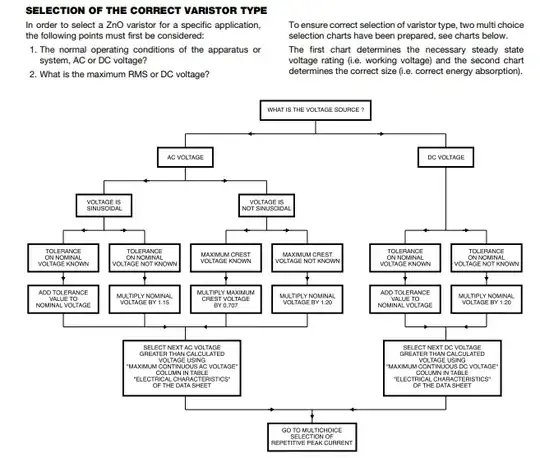
To prevent "high voltages" transient, use a VDR (MOV).
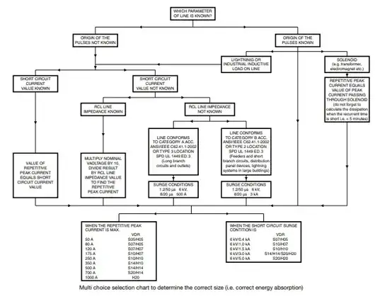
See this for a correct choice of VDR
How to choose chart in the just above note ...


Current will be limited (roughly) by AC and DC resistance in series. Magnetic field, and thus, force will be sinusoidal. Required force depends on what you want to kick.
– Vladimir Jul 23 '22 at 14:07