1

In the following Figure 1 and Figure 2, the sensor is the one in dashed box. The output impedance of the sensor is big and in this case is 1k Ohm.

And as you see regardless of the sensors are bipolar or single-ended output, the sensor ground is shared with the InAmp's AI GND. So in Figure 1 and 2 the sources are not truly floating correct?

schematic

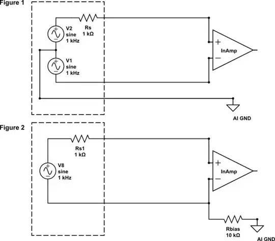
simulate this circuit – Schematic created using CircuitLab

On the other hand in below Figure 3, the same sensor's signal and ground first goes to this signal cond. module and then to the InAmp. There is truly isolation so we can say truly floating. The inputs are floating with respect to AI GND and the power supply common.

schematic

simulate this circuit

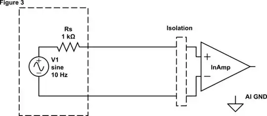
Why does in Figure 1 and Figure 2 the 1k output impedance matter for common mode noise but not in Figure 3? How can this be explained by using diagrams and current flows ect. for clarity?

After reading Andy Aka's answer here are the models for above scenarios and sim results:

enter image description here (left-click to zoom in)

user1245
  • 4,125
  • 4
  • 38
  • 95
  • These scenarios can be proven by using a simulation tool. Most engineers would use a sim to understand this. Have youg a reason for not using one. They are free and might be a steep learning curve, but well-worth the effort. – Andy aka May 24 '18 at 13:29
  • That would be really great I agree. I can actually simulate Fig 1 and Fig 2 circuits. But I have to model the CM noise and "isolation barrier" where I would have difficulty. Is there a workaround? – user1245 May 24 '18 at 13:33
  • Fig 3 doesn't need an isolation barrier because the input impedance of the diff amp can be assumed to be balanced AND high impedance. See my wordy answer. – Andy aka May 24 '18 at 13:38

1 Answers1

1

For scenario 1 just replace the voltage sources with 0 volts i.e. forget about your wanted signal - just imagine your signal is 0 volts. Then imagine an interference source of (say) 1 MHz of which one side is grounded and the other side connects to line A via a 1 nF capacitor and line B also via a 1 nF capacitor. Then ask yourself which line is going to show signs of interference; the line that is in-effect grounded (line A), or the line that has 1 kohm to ground (line A)?

For scenario 2 use the same idea and note that line A looks like 10 kohm to ground whereas line B looks like 11 kohm to ground. Which line will receive more interference?

I'd set up my simulator to look at the problem this way: -

enter image description here

enter image description here

Andy aka
  • 456,226
  • 28
  • 367
  • 807
  • Woow thanks a lot, so this is the way of thinking.. Could you also add for the scenario Figure 3 so the answer would be complete? Your models also can be simulated thats really cool- – user1245 May 24 '18 at 13:45
  • Regarding Figure 3, for SPICE to run can I put 100Meg between the noise GND in the middle and the AI GND? Does that make sense? – user1245 May 24 '18 at 13:53
  • The noise ground should have been labelled AI GND. I'll fix. – Andy aka May 24 '18 at 13:56
  • Please see my edit I made an attempt to simulate all these. I just used resistors instead of diff amp for simplicity. Simulations agree with your previous answer that the output impedance is taken care of in Figure 3. Let me know if it is correct. Thanks – user1245 May 24 '18 at 14:26
  • It certainly looks OK and thankfully agrees with my answer!! – Andy aka May 24 '18 at 14:32