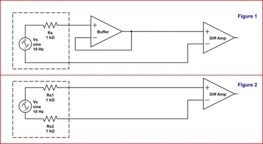
This is a generic question for about frequency sensors. But as an example I use this sensor which has around 1k output impedance. So in below drawing the source in dashed box has 1k output impedance:
simulate this circuit – Schematic created using CircuitLab
The voltage signal from the source to the receiver will be transmitted by STP cable. And the receiver is a sort of differential input instrumention amplifier.
But the system is not 100% balanced because of the 1k output impedance.
I think the best way is to buffer both signal and ground of the output for balancing but this would introduce some noise.
Assuming GND has very low impeance, In Figure 1 the 1k is lowered by a buffer. And on the other hand in Figure 2 the imbalance issue is tried to be solved by adding a 1k resistor on the ground output.
My questions are:
1-) If I use a resistor as in Figure 2, then I would increase DC error but I can calibrate it out. In that case can we say that Figure 2 is a better solution than Figure 1? I'm asking because in Figure 1 the buffer circuit will introduce noise.
Which one is better than the other?
2-) Would you measure the exact value of the output impedance or would you rely on the datasheet?