7

I'm building a simple Z80 breadboard computer for my hobby. In this question I use Z80 as an example, but I think this may apply to many CPUs that allow for bus sharing.

The problem is as follows. Z80 has a pin called BUSREQ, which after being pulled low, makes the CPU stop it's execution, and float the address, the data and a few control pins to allow for another device to control them. This is an awesome feature I plan to use to program the ROM without having to disconnect/rewire things.

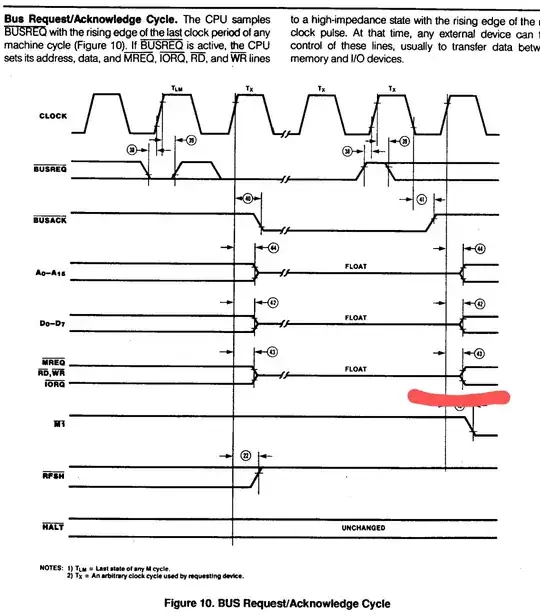
If we take a look at the data sheet, after we pull the BUSREQ pin high again, to give the control back to Z80, we see that after changing BUSACK, confirming that the bus can no longer be controlled, there is a bit of a delay, that I highlighted.

This means, that if my ROM-programmer let's go of the bus like a good citizen, pins will float until the CPU controls them. This is not a big problem for the address and the data, but a pretty serious problem for the WR pin, which controls writing to memory. If I understood correctly, at the end of bus sharing, floating pins have the reign over my memory, potentially overwriting it.

This is especially a problem for me, since for hobby purposes I use a 3hz clock for the setup, making the floating time extremely long.

A solution that I came up with to solve this, is to have a multiplexer controlled by the programmer. The high WR signal would be held a little after BUSACK goes high.

But it keeps bugging me, there must be a better solution than external circuitry? Or maybe it doesn't matter that much? What was the thought in making the lines float that short time after?

enter image description here

JamMaster
  • 173
  • 3

2 Answers2

6

Maybe I'm overlooking something, but why not use pull-ups (or pull-downs, whatever is required for a safe state) on all control lines?

Michael Graf
  • 10,030
  • 2
  • 36
  • 54
  • From what I understand (I'm a noob), is that you usually use pull-ups/downs when it comes to open collector outputs, is that correct? What happens when you use a pull-up with a tristate pin that's high or low? – JamMaster Mar 22 '20 at 11:19
  • 4
    You use pull-ups on open-collector outputs because otherwise you don't get logic high. With tristate outputs, when the output is enabled, it will easily overpower the weak pull-up, but when it's tristated, it will slowly float the pin high. The pull-up value must be also strong enough to overpower leakage current and to set a valid logic level within some sensible time. – Justme Mar 22 '20 at 11:37
  • What do you mean by weak and strong here? And how does time come into play when we're talking about simple resistors? I am using 10k resistors for pullups and downs. Also, what do you mean with overpowering? It would make sense when talking about currents, but oftentimes these circuits are done with cmos technology, which operates on voltages. How should I calculate the resistor values for that? – JamMaster Mar 22 '20 at 15:02
  • 1
    @JamMaster: Short answer: 10k resistors will be fine for a Z80 on a breadboard, as will be 4.7k, or 22k. The point is to assert a defined voltage when all components are tri-stated, while avoiding too high a current when they are not. – Michael Graf Mar 22 '20 at 15:09
  • 3
    Long(ish) answer: "high impedance" isn't "infinite impedance", plus there's some capacitance both in the board and in the ICs itself that may need to be charged/discharged. What you want the pull-up to do is pull, say /WR up fast relative to your clock speed. If you want to do the math, check the datasheets for Input Leakage Current and Input Capacitance. – Michael Graf Mar 22 '20 at 15:17
  • 1
    Thank you, that's exactly what I was looking for. I knew there was a simpler solution for this! – JamMaster Mar 22 '20 at 16:08
  • 3
    One might add that if /WR is already high before the line is tristated, then all the pullup needs to do is keep it high, and for that the time constant doesn't matter. – Mike Spivey Mar 22 '20 at 18:23
  • 1
    That is true, so only thing to worry about is the load. For high-impedance CMOS chips, 10k should be fine. But TTL chip inputs do draw current, and 10k can be too high. Depending on how many TTL chips there are the pull-up resistance may need to be lowered down for it to keep voltage above input high threshold of all chips, but not too low so that the original output driver can still pull it below input low threshold of all chips and without exceeding rated current limit. – Justme Mar 22 '20 at 21:25
  • @MikeSpivey: I wonder why CMOS devices back in the day didn't include "bus keeper" circuits which would act as a weak pull-up when pins were high, and a weak pull-down when they were low? If one ensures that pins would get actively driven for part of a cycle, they could then switch to bus keeper mode before the next device took over the bus by driving strongly. – supercat Mar 22 '20 at 22:24
  • @Justme true TTL (like in 74LS, 74ALS and not like in 74HC/HCT) inputs are already act as a kind of pullup, so that they source current only when pulled down to logic 0. – lvd Mar 24 '20 at 12:54
0

If I'm reading that diagram correctly, the Z80 expects bus control to transfer (either way) synchronously with the rising edge of the clock. The diagram shown is scaled to match a typical clock speed of several MHz, but the time between the clock edge and the control lines being driven will be independent of the actual clock speed.

You could handle this cleanly by employing a D flipflop to gate the /BUSACK signal from the CPU, clocked by the rising edge of the CPU clock, and use the output of that to govern the tristating of your external control/address signals. They will go high-impedance just as the CPU starts driving the same lines, so there will be no significant period of floating overall.

Chromatix
  • 16,791
  • 1
  • 49
  • 69