0

x and y can be plotted for the 2D trajectory of a projectile by the following two primary equations.

$x = v t \cos \theta$

$y = vt \sin \theta - \frac{1}{2} g t^2$

$where:$

$v = initial \, velocity$

$t = time$

$\theta = launch \, angle$

$g = acceleration \, due \, to \, gravity$

Can equations be derived for the x and y trajectory of the projectile if the trajectory is altered, by a given angle at a given x,y point?

I want to completely ignore momentum, air resistance, etc.

I have found it trivial to calculate the resulting trajectory using "brute" methods when the path is reflected at a perfect horizontal or vertical angle, and it may even be trivial to reflect at 45 degree angles, such as coming into contact with a flat wall, or horizontal surface, or perfectly 45 degree surface. The problem I have is I need (for coding) a way to handle contact with a surface at any 360 degree angle.

I don't want to calculate any loss of momentum from the impact of the collision at the x,y point.

I'm not sure what the proper term is for what I'm asking for, I describe what I'm trying to do as "reflecting" or "mirroring" a trajectory about a given angle at a given point.

EDIT: I've drawn a graphic to illustrate what I'm trying to say example

The top black trajectory represents a projectile's trajectory undisturbed fired from x-3,y0.

The bottom blue trajectory represents the same projectiles trajectory if it was disturbed by a 90 degree (straight up/down, or vertical) line, which the trajectory reflects off of based on the angle of the line at the point of contact (that point is x0,y2.5.)

The gravity is the same, towards the horizontal plane, or the "ground", before and after reflection, it's not changed in any way, merely the trajectory changes direction.

This is trivial to solve for a 90 degree line, or 180 degree line, or maybe 45 degree lines, but a formula or equation which plots x and y of the trajectory after the x0,y2.5 point, no matter what angle the line is at there at x0,y2.5, is what I'm after.

Luke Allen
  • 301
  • 5
  • 16

2 Answers2

1

I would like to modify your original equations slightly by affixing subscripts to $v$ and $\theta$ to acknowledge the fact that they use the angle and speed of the projectile's motion at a particular point in space and time, namely, at the initial point $(x,y) = (x_0,y_0)$ and time $t = t_0$, 
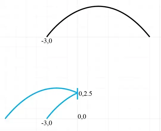
and also to take into account that $x_0$, $y_0$, and $t_0$ are not necessarily all zero. (In particular, in your example in the question, $x_0 = -3$.) The result is \begin{align} x &= x_0 + v_0 (t-t_0) \cos \theta_0, \\ y &= y_0 + v_0 (t-t_0) \sin \theta_0 - \tfrac12 g (t-t_0)^2. \end{align} There are other ways to express this, but this form of the equations is relatively simple to write. (The equation measures the "extra" amount of $x$, $y$, and $t$ past the point $(x_0,y_0)$ and time $t_0$.)

We now consider another point in space and time further along the initial trajectory, at the point $(x,y) = (x_1,y_1)$ and time $t = t_1$. Note that you can uniquely determine $x_1$ and $y_1$ for any $t_1$, you can uniquely determine $t_1$ and $y_1$ for any $x_1$, and given a $y_1$ there are either two possible solutions, one possible solution, or no possible solution for $t_1$ and $x_1$. But however you decide to determine the values, we want to know all three values $x_1$, $y_1$, and $t_1$.

We also want to know the speed $v_1$ and angle $\theta_1$ of the initial trajectory as it reaches $(x_1,y_1)$. Taking the horizontal and vertical components of the velocity at time $t$ as a function of $t$, we have \begin{align} v_x(t) &= v_0 \cos \theta_0, \\ v_y(t) &= v_0 \sin \theta_0 - g(t-t_0). \end{align} The speed at time $t$ is therefore \begin{align} v(t) &= \sqrt{(v_0 \cos \theta_0)^2 + (v_0 \sin \theta_0 - g(t-t_0))^2}. \end{align} The angle of motion at time $t$ is either $$ \theta(t) = \arctan\frac{v_0 \sin \theta_0 - g(t-t_0)}{v_0 \cos \theta_0} \quad\text{or}\quad \theta(t) = \arctan\frac{v_0 \sin \theta_0 - g(t-t_0)}{v_0 \cos \theta_0} + \pi $$ depending on whether $\cos\theta_0$ is positive or negative, respectively. I'll assume from here on that $\cos\theta_0$ is positive. So at time $t = t_1$, the speed and direction of the projectile are \begin{align} v_1 &= \sqrt{(v_0 \cos \theta_0)^2 + (v_0 \sin \theta_0 - g(t_1-t_0))^2}, \tag1\\ \theta_1 &= \arctan\frac{v_0 \sin \theta_0 - g(t_1-t_0)}{v_0 \cos \theta_0}. \tag2 \end{align}

Now suppose there is a flat surface through the point $(x_1,y_1)$ at angle $\alpha$, where $\alpha$ is the angle between that surface and the positive direction of the $x$ axis; that is, $\alpha = 0$ for a horizontal surface, $\alpha=\frac\pi2$ ($90$ degrees) for a vertical surface, and $\alpha=\frac\pi4$ ($45$ degrees) for a surface at $45$ degrees from horizontal, sloping upward to the right. If we have perfect reflection of a projectile moving in the direction $\theta_1$ as it strikes that surface, the reflected path of the projectile will start at the angle $2\alpha - \theta_1$.

So what we need to do is to reapply the equations for projectile motion, but substitute $2\alpha - \theta_1$ as the new "initial angle", and translate the "initial position and time" from the point $(x_0,y_0)$ and time $t_0$ to the point $(x_1,y_1)$ and time $t_1$. We do this by substituting $x_1$ for $x_0$, $y_1$ for $y_0$, and $t_1$ for $t_0$ in the equation of motion. The result is \begin{align} x &= x_1 + v_1 (t - t_1) \cos (2\alpha - \theta_1), \\ y &= y_1 + v_1 (t - t_1) \sin (2\alpha - \theta_1) - \tfrac12 g (t- t_1)^2, \end{align} where $v_1$ and $\theta_1$ are defined by Equations $(1)$ and $(2)$ above. You can further manipulate these equations algebraically to get them into the exact form you would like.


Alternative method

Another way to derive a formula is to use a little linear algebra. We still need $x_1$, $y_1$, and $t_1$ at the point of impact on the flat surface, but we avoid explicitly computing the speed or angle of the incoming trajectory at that point.

We do still need to think about the velocity of the projectile before and after the collision, but instead of speed and direction, we use the $x$ and $y$ components of velocity, $v_x$ and $v_y$, more directly. It will help to represent the initial velocity in this form as well, that is, set \begin{align} v_{0x} &= v_0 \cos \theta_0, \\ v_{0y} &= v_0 \sin \theta_0 \end{align} so that $v_{0x}$ and $v_{0y}$ be the $x$ and $y$ components of velocity at the start of the first part of the trajectory. The equation of the trajectory can then be written \begin{align} x &= x_0 + v_{0x} (t-t_0), \\ y &= y_0 + v_{0y} (t-t_0) - \tfrac12 g (t-t_0)^2. \end{align}

The components of a velocity vector at a later time $t$ in this part of the trajectory are then $$ \begin{pmatrix} v_x(t) \\ v_y(t) \end{pmatrix} = \begin{pmatrix} v_{0x} \\ v_{0y} - g(t-t_0) \end{pmatrix}. $$ (I have put the components of the vector together in a $2\times1$ matrix here because it is a convenient format for linear algebra. Rest assured that we'll stop using this format when we get to the final answer; I am using it just for the derivation of formulas.)

The next step will be to apply a transformation matrix to reflect this vector around a line parallel to the flat surface, passing through the origin. The reason we want the line to pass through the origin is because vectors have no fixed "starting" position, only a direction and magnitude; but if you imagine the "tail" of the vector at the point $(0,0)$, then the transformation we want will leave the "tail" of the vector in place and only move the "head".

We now have two choices on how to proceed, depending on how we represent the inclination of the reflecting surface.

Using the angle of the surface. If the reflecting surface makes an angle $\alpha$ with the $x$ axis, then the reflection matrix is $$ \begin{pmatrix} \cos(2\alpha) & \sin(2\alpha) \\ \sin(2\alpha) & -\cos(2\alpha) \end{pmatrix} $$ (as shown in this answer to another question), and the reflected vector is found by multiplying the incoming vector by this matrix on the left. The resulting vector is \begin{align} \begin{pmatrix} v_{1x} \\ v_{1y} \end{pmatrix} &= \begin{pmatrix} \cos(2\alpha) & \sin(2\alpha) \\ \sin(2\alpha) & -\cos(2\alpha) \end{pmatrix} \begin{pmatrix} v_{0x} \\ v_{0y} - g(t_1-t_0) \end{pmatrix} \\ &= \begin{pmatrix} v_{0x} \cos(2\alpha) + (v_{0y} - g(t_1-t_0)) \sin(2\alpha) \\ v_{0x} \sin(2\alpha) - (v_{0y} - g(t_1-t_0)) \cos(2\alpha) \end{pmatrix} \end{align}

Writing this as a system of equations without matrices, \begin{align} v_{1x} &= v_{0x} \cos(2\alpha) + (v_{0y} - g(t_1-t_0)) \sin(2\alpha), \tag3\\ v_{1y} &= v_{0x} \sin(2\alpha) - (v_{0y} - g(t_1-t_0)) \cos(2\alpha). \tag4 \end{align}

Using the slope of the surface. If the slope of the reflecting surface is $m$, that is, the surface is parallel to the line $y = mx$, then the reflection matrix is $$ \frac{1}{1 + m^2}\begin{pmatrix} 1-m^2 & 2m \\ 2m & m^2-1 \end{pmatrix}. $$ (See this question and its answer.) The reflected vector is therefore $$ \begin{pmatrix} v_{1x} \\ v_{1y} \end{pmatrix} = \frac{1}{1 + m^2}\begin{pmatrix} 1-m^2 & 2m \\ 2m & m^2-1 \end{pmatrix} \begin{pmatrix} v_{0x} \\ v_{0y} - g(t_1-t_0) \end{pmatrix}. $$ If you do the matrix multiplication, the result is equivalent to the system of equations \begin{align} v_{1x} &= \frac{1}{1 + m^2}((1-m^2)v_{0x} + 2m(v_{0y} - g(t_1-t_0))), \tag5\\ v_{1y} &= \frac{1}{1 + m^2}(2m v_{0x} - (1-m^2)(v_{0y} - g(t_1-t_0))). \tag6 \end{align}

Of course this does not work for a vertical line of reflection, but in that case we simply change the sign of $v_x$ at the point of impact.

Assembling the final result. We already know how to write the equation of a trajectory that starts with given $x$ and $y$ velocity components from a given point at a given time; all we need to do is to take the values of $v_{1x}$ and $v_{1y}$ (either from Equations $(3)$ and $(4)$ or from Equations $(5)$ and $(6)$) and plug them into these equations: \begin{align} x &= x_1 + v_{1x} (t-t_1), \\ y &= y_1 + v_{1y} (t-t_1) - \tfrac12 g (t-t_1)^2. \end{align}

While this may seem like a long procedure, most of the writing above is just explanation and proof; to actually use the procedure, after determining $x_1$, $y_1$, and $t_1$ you merely take four of the equations above (selecting the ones that suit the way your surface is described) and start evaluating them, using the known data.

David K
  • 98,388
  • This seems exactly right, thank you!! – Luke Allen Apr 11 '16 at 13:14
  • Note that the "original" equations did not take into account starting the first part of the trajectory at $x=-3$ and $y=0$, so I've written that into my "original" equations now. This makes the "original" equations a little more complicated, but it also makes it easier to rewrite them to get the equations for the reflected trajectory. – David K Apr 11 '16 at 13:15
  • Yes, I understand perfectly now, this question has been on my mind for two weeks. I always thought it was possible to calculate the resultant angle after collision based on the initial angle, initial velocity, and initial position alone - without calculating the $ /theta , 1$ and $v 1$ as you call them, but now I see. Thank you, I'm sure this will help others too, very clear manner of answering! – Luke Allen Apr 11 '16 at 13:20
  • I think you mentioned that you are a programmer. If so, you probably appreciate how useful it is sometimes to define an auxiliary variable or "helper" function that is not part of the original specification of the program. Variables such as $v_1$ and $\theta_1$ are something like that. – David K Apr 11 '16 at 13:41
  • David, the more I think about it, shouldn't it be possible to plot the x and y without calculating the impact angle and velocity with the line? The horizontal velocity doesn't change since there is only downward gravity, and in the case of colliding with a perfectly vertical line, the trajectory is mirrored by the vertical, no matter what impact angle there is. I ask out of curiosity only – Luke Allen Apr 12 '16 at 11:25
  • @LukeAllen Indeed you are right; it is not necessary to explicitly calculate the angle and magnitude of the velocity vector. The explanation of how to do this is (I think) a little more complicated than if you have an explicit angle, but the formulas that you end up using are in some ways simpler (no arc tangents or square roots to evaluate!). I might prefer one of these methods if I were writing software to do this. – David K Apr 13 '16 at 00:34
  • David, thanks so much, I hate to ask for more, but I've tried implementing the first way and alternative way (equations 3 and 4) into coding but nothing is working. I'm sure, after much trial and error, I've got the equations in exactly as you have them, with one exception: I have to put the angle in as radians, since my prog lang doesn't support cos(Degrees) or sin(Degrees), the number must be radians there. Could that be causing the problem? The trajectory plots correctly up until I try to account for a line obstructing it. – Luke Allen Apr 13 '16 at 13:38
  • I meant that I'm inputting radians, not degrees, and it's not working. I just realized your equations were counting on radians the entire time anyway. I have no clue why all methods aren't working. Perhaps it's because on a computer, Y values get bigger as you get lower on the screen, and less as you get higher, which is the opposite of a typical plot graph. I tried reversing some + and - signs in the equations to account for this, it worked for the normal trajectory, but with the line-reflection part, nothing even came close to an accurate result – Luke Allen Apr 13 '16 at 15:14
  • Disagreements over the sign of the $y$ coordinate could cause some weird results. The "alternative" methods are particularly susceptible; they'd probably have to change in several places to support "$y$ points down". The approach I've usually seen in dealing with graphics is to do everything in "world" or "model" coordinates (which could have $y$ increasing upward) until you actually display something, when you transform to window coordinates. One way is to choose a positive value of "world" $y$ to put at the top of the window, and subtract all other "world" $y$ values from that. – David K Apr 13 '16 at 16:13
  • I'm still trying to use this and it works 50% of the time using your first solution. The problem is whenever the wall is kind of flat (or exactly flat) the \begin{align} y &= y_1 + v_1 (t - t_1) \sin \theta_1 - \tfrac12 g (t- t_1)^2, \end{align} seems to not work out correctly. – Luke Allen Jun 12 '16 at 19:35
  • I just noticed that the paragraph before that formula says that $\theta_0$ in the "before the bounce" formula should be replaced by $2\alpha - \theta_1$; but then I mistakenly wrote just $\theta_1$ instead of $2\alpha - \theta_1$. (I have fixed that error now.) It'd be surprising if this ever gave results that look OK; writing $\theta_1$ instead of $2\alpha - \theta_1$ has the effect of "keep going in the same direction as if the wall weren't there." If the corrected formula doesn't fix things we may need to look at the actual plots for a few known sets of input values. – David K Jun 12 '16 at 22:07
  • I was using $2\alpha - \theta_1$ all along. The easiest case to solve I guess is all cases involving a perfectly flat (horizontal) wall. The first solution (all actually) I've tried always fail at those scenarios. They also fail at any scenario that seems to be somewhat flat, however there is no fixed wall angle (such as less than 30 degrees) that makes it fail, it's dependent on both the arc of the shot and the wall angle, except it seems for the completely flat wall case or ones very close to it. – Luke Allen Jun 13 '16 at 01:24
  • http://i.imgur.com/MzaD12k.png That is a link to a sample plot of the formulas so you can see what it's doing. On the left where the red line starts is the initial position of the projectile. It is fired at 45 degrees slanting up and to the right. It has an initial speed of "50" arbitrary units. The line is not very smooth intentionally, each line segment is one time step. At approximately the same elevation as the initial firing position I created an imaginary wall to bounce off of. What happens is the incorrect result of going up forever and not obeying gravity. – Luke Allen Jun 13 '16 at 01:32
  • The correct result for the above image would basically be two arcs that are identical (I think). This is not colliding with the ground with loss of force but a frictionless "reflector line." It does appear after the first timestep line segment after the invisible horizontal wall (which is there programmatically of course) the trajectory is reflected correctly, it just seems to not obey gravity any more, even though that hasn't changed in my program, in fact the only gravity is in the equation itself. – Luke Allen Jun 13 '16 at 01:41
  • My wild guess is the original equations in my original post (taken from wikipedia) somehow handle gravity differently than the equations in your solutions, somehow using your solutions, only some of the time, gravity becomes "inverted", but I don't know how that could be. – Luke Allen Jun 13 '16 at 01:42
  • The original equation had $-\frac12gt^2$ for gravity; the "after bounce" equation has $-\frac12g(t-t_1)^2$. It's hard to see how that could become "inverted" unless the implementation introduced an extra sign change somehow. – David K Jun 13 '16 at 11:30
  • There are multiple weird things in the graph at http://i.imgur.com/MzaD12k.png. Aside from wrong-way curvature, the angle of reflection is not correct for a horizontal surface (the projectile comes in steeper than it leaves), and the graph after reflection is much less curved than before. It doesn't appear to be a graph of the equation in the answer at all. – David K Jun 13 '16 at 12:14
  • I've found out something, it is not the angle of the wall and projectile that directly gives the wrong plot. If the resulting reflection requires that the projectile not reverse X direction, but instead continue going in the same X direction, except with an altered trajectory, THAT is when the plot doesn't work and the only time it doesn't work. Which is why a flat wall always results in a bad result, as a flat horizontal wall never reverses X direction. – Luke Allen Jun 13 '16 at 14:37
  • I still don't know why the equations can't handle a same-X-direction reflection but it appears that the equations perfectly handle all "rebounds" but not "glancing bounces" like this one http://cdn1.askiitians.com/Images/2015316-105914119-5693-Untitled-1.png – Luke Allen Jun 13 '16 at 14:37
  • It appears the provided equations try to force a "rebound" behavior, and it won't work for the "glancing" bounces. Here is a plot showing this behavior, this should've resulted in a glancing bounce, but the equations seem to try to force a rebound, so the plot actually "curves back" slowly, on the far left hand side of the image you can see the graph come back down from off-screen as it did a big "loop". The thick red line is the Y axis, the thin vertical line is the peak of the trajectory before the bounce. imgur.com/fGfYVNd.png – Luke Allen Jun 13 '16 at 14:37
  • This kind of explains why it looks so weird, it's trying to reverse X direction for any scenario. However it appears (incorrectly) to arc back the X direction very slowly in most "glancing" cases, going off-screen before I see it come back down. I've been struggling with this it feels like for months but it feels closer than ever to revealing the exact reason for this anomaly. – Luke Allen Jun 13 '16 at 14:39
  • No, the equations do not try to force the $x$ direction to reverse. If $\alpha=0$ then $\cos(2\alpha-\theta_1) = \cos(-\theta_1) = \cos(\theta_1)$, so the $x$-velocity will be in the same direction at the same speed. The plots you're getting simply do not represent the equations as written above. Perhaps it's time to take the source code of the program that produced these plots over to stackoverflow or the code review SE to find out why it produces graphs that curve upward. – David K Jun 13 '16 at 16:44
0

I am also interested in this problem. I would like to share some thoughts here.

If we treat the problem as one of reflection, then we must say which side of the mirror is silvered ( reflecting side of the mirror). For the lower blue curve (let us call it 'past')and the vertical position of mirror with left side mirrored, the top blue curve will not be the reflection(image). On the other hand, if we have the right side of the parabola ( which if call the 'future') and if the mirror is silvered on the right side then the reflection would be the top blue curve. In other words, if the object and the position of the mirror are specified, we know the shape and position of the image. The top and the bottom blue curve do not correspond to object and image in the left side silvered vertical mirror in the positions shown. So what we are seeking is not a simple reflection. Future reflected cannot give past or past reflected cannot give future. Elastic collision problem and reflection have some similarities and some dissimilarities. For example mass plays no role in reflection of light.

user55356
  • 101