I'm looking at making my own USB cable for a project. The primary issue I'm having is that I'm getting a lot of capacitance in my cable between D+ and D- (400ish pF) which is enough to throw off the signals being read by my pc. Is there an easy way to fix this? I understand this is an impedance matching issue, but I'm not sure where to begin with this one since the capacitance is between two input lines, not one line and ground which is what I remember from my electromagnetics course.
Asked
Active
Viewed 6,322 times
3 Answers
2
The impedance of the data line is determined by
- capacitance between wires and
- inductance of the pair of wires.
It's a simple formula and I've used it to make custom cables for high speed data links in circumstances where the wires and overall covering needed to be made from PTFE material to suit high temperature applications. The formula is
Zo = sqrt(L/C) - this is the impedance for a lossless line. Here is a good article.
This tells you that to make a higher impedance cable L needs to grow and/or C needs to reduce. One of the methods is to make the actual conductor a smaller diameter whilst keeping the spacing between conductors the same. Or you can make the spacing between conductors bigger. Below is a picture of an on-line calculator: -
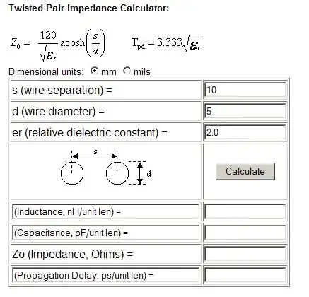
Note that the formula given on the page above (Zo) is exactly the same as the one I gave earlier but it uses the more fundamental properties of wires to give L and C. In other words, permeability and permittivity are built into the equations but the 2nd formula explicity lists permittivity because that will be a variable due to the insulation type.
And here is the link to the webpage for the calculator. Please note that there are several calculators on-line so you can double check other ones.
From memory USB cable impedance is 90 ohms.
And if all this seems to much trouble, just make the wires thinner and space them apart a bit more and see what happens. If it is a Zo issue then things should begin to improve as you do this.
Andy aka
- 456,226
- 28
- 367
- 807
1
Well, normal USB cables have these shielding to decrease line capacitive effect. My initial guess: Why don't you try to shield them at first to see if the capacitance is the result of the physical cabling. Also having a twisted pair in USB cable might help to decrease the capacitance in between lines, see USB cable construction.
kunguz
- 51
- 3
-
Normal USB cables have shielding OUTSIDE the twisted D+/D- pair. That wouldn't help reduce the capacitance in between the two cables. I also have my custom USB cable in twisted pair arrangement right now. I understand that buying a "legit" 4 meter long cable would probably fix my problem but I want to know if there's any engineering principle I can use to apply a fix to this. I will need the custom USB cable for a high-temperature application. – Shensmobile May 17 '13 at 14:35
0
Thinking about it some more, I think it'd be hard to get a large enough inductor to counteract the capacitance, but still keep it small enough to not degrade the USB signal, especially at USB 2.0 data rates (480 Mbit.)
For long USB runs, if you can't alter the physical construction of the cable sufficiently, then active amplification is needed. And, yes, it has to be bi-directional. You can actually buy ready-made cables with built-in amplification, and you can also buy chip sets that you can add to your cable.
Jon Watte
- 5,670
- 27
- 37
Unfortunately I can't space the wires out more, or make the wires much smaller, so I think picking a different insulator would be my only choice.
– Shensmobile May 17 '13 at 16:12