Below is a flow diagram of the process; the missing piece is the box in red
... that's otherwise known as an X-Y problem. As you'll soon see, that's only a missing piece if you have a very particular solution in mind. Other solutions exist and may be easier to implement (!).
If that cell can accommodate the input current of an LM397 - about 1nA - then all you need is that one comparator really, and a voltage reference. The whole circuit can be adapted to run from any supply between 6V and 24V, but as shown below it'll work from 12V to 24V, with an adjustment to R3 as further described.
It operates from a single supply, and the supply doesn't need to be terribly well regulated.
Whoever provides the cell should specify what is the maximum output current that it can provide without degradation/shortening life span below the datasheet spec. So you should know whether 1nA is OK or not. If a lower input current is desired, there are more modern R-R (rail-to-rail) input CMOS comparators that have input current orders of magnitude lower.
Something like the following would work, and costs <$10 excluding the PCB/breadboard.
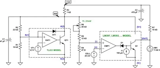
simulate this circuit – Schematic created using CircuitLab
The "TL431 MODEL" and "LM397...MODEL" are simulation equivalents of TL431 and LM397/393 chips, respectively. CircuitLab doesn't have TL431 nor LM397 device built-in, so I had to make them from existing devices in the simulator. In a physical circuit use the actual TL431 and LM397 chips in place of the models.
The circuit works as follows:
R3-C1 is the low-pass power supply filter. C2 filters the incoming supply voltage.
R1-R2 provide feedback to the TL431 shunt voltage regulator. It generates a clean 8.0V supply and reference for the rest of the circuit.
R4-R6 are a threshold voltage divider, and provide between 10-30mV reference to the comparator - depending on the setting of R6. The comparator compares the threshold to the cell voltage, and generates an output voltage that swings between the 12V supply and ground.
The comparators shown are sensitive enough that there's no need to amplify the signal prior to comparing it to a threshold voltage. The comparators won't be particularly fast, and will react in say less than 1ms - that should be plenty fast for the application you have. Amplification would be needed if you wanted the comparators to react much faster than that, say in 10μs - but I doubt there's any need for that in your application.
The supply voltage can be between 12V and 24V. R3 should be 1kΩ for 12V supply, 2.2kΩ at 24V supply, and some value between for supplies between these two limits. Its value doesn't need to be precise - 20% accuracy will do. For supplies above 12V, R3 should be a 0.5W part, or two 1/2 value resistors in series. E.g. for 24V, R3 could be 1kΩ + 1kΩ in series. R3 is expected to be warm/hot to touch.
LM397 is just one device from a large family of comparators that come in single, double and quadruple packages. Any one of the following can be used. In case of multi-device packages, connect unused comparator inputs to GND. The following chips carry the basic "LM397" comparator inside, in various quantities:
- LM397 - x1
- LM393, LM2903 - x2
- LM339, LM2901 - x4
Any of the chips above will work - it really is the same comparator circuit in single, dual and quad packages. Choose whatever is the cheapest. If you're going for elegance, then LM397 is what you actually need as it doesn't have any extra comparators that would sit unused. But nobody really cares much - those are so-called jellybean parts, widely available, and all equivalent.
Add a 555-based timer to this circuit, and you got yourself a complete, dirt-cheap solution, without need for external timers. Even adding a 555 the whole thing would still be well under $20 for parts, quantity 1.


