simulate this circuit – Schematic created using CircuitLab
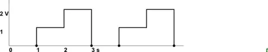
Figure 1. A simple periodic waveform stepping from 0 to 1 to 2 V.
Let's assume a 1 Ω load to make it easy.
Average voltage
The average voltage over the period (3 s) is \$ \frac {0 + 1 + 2} 3 = 1 \ \text V \$.
If we use that to calculate the average power in 1 Ω we would get \$ P = \frac {V^2} R = \frac {1^2} 1 = 1 \ \text W \$.
RMS voltage
simulate this circuit
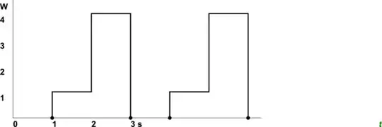
Figure 2. The power waveform for the voltage of Figure 1 into a 1 Ω load.
RMS is the Root of the Mean (average) of the Squares:
$$ V_{RMS} = \sqrt {\frac {V_{01}^2 + V_{12}^2 + V_{23}^2} 3} = \sqrt {\frac {0 + 1 + 4} 3} = \sqrt {\frac 5 3 \ \text V} = 1.29 \ \text V $$
If we use that to calculate the average power in 1 Ω we would get \$ P = \frac {V^2} R = \frac {1.29^2} 1 = 1.66 \ \text W \$.
Why the difference?
The higher voltage (2 V) portion of the waveform has a much more significant contribution to the mean power due to the square law. You miss that if you take the average first.
We use the RMS value of a waveform to find that DC voltage that would give the equivalent power, not the average voltage. In the more general case (not using simple rectangular waves as I have here) you would use calculus to integrate the area under the curve of the voltage (or current) squared.