I'm modelling a wind turbine and PMSG with uncontrolled rectifier and buck converter. I am currently trying to design a current controller for the current Iq coming from the generator. To do so, i linearized the entire system. I previously attempted to design PI controllers for the systems but controllers that worked for the linear system did not work for the non linear system and vice versa. However, using the "linearize" command in Simulink which- the bode plot generated for the linear transfer function of the system and for the non linear model are exactly the same.
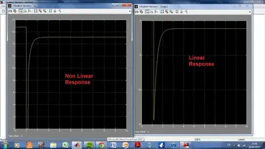
Now I am comparing the step responses of the linear and non linear system, which i am expecting should be the same for a small step (0.5). By stepping the duty cycle of the converter, the following step responses for the linear and non linear system were found. Does anyone have any idea what might be wrong?
N.B. ignore the fact that the response of the linear system starts at 0 and goes negative- i am mostly interested in the amount severity of the drop in current in the case of the non linear system and the time it takes before rising back up again.