1

I've never used Arduino before, so I'd be really grateful if any errors in the following circuit could be pointed out to me:

enter image description here

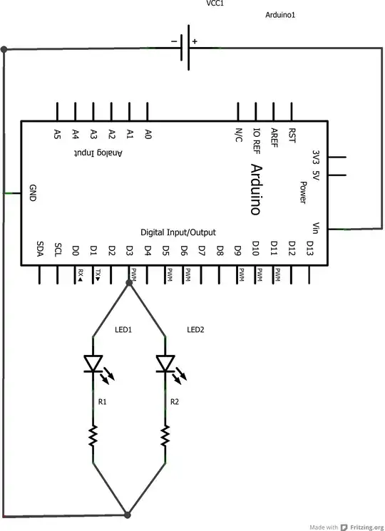
As far as I understand it, I have two super-bright LEDs connected in parallel each with their own resistor. I've connected these to one of the digital pins which I think can give 5V each. The resistors are 100 ohms for these LEDs (these green ones)?

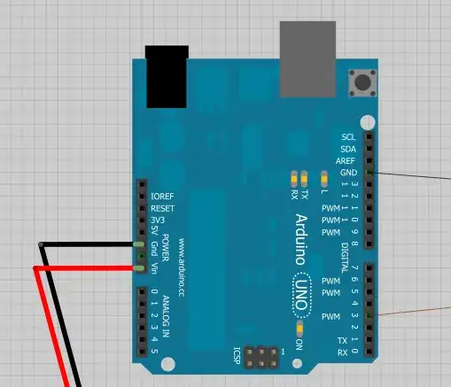
In terms of the power setup, I have a 9V battery with the positive terminal connected to Vin power pin and the negative to the Gnd power pin which I think powers the board. The wire after the resistors then goes to the Gnd pin on the other side of the board with the digital pins:

enter image description here

As a side note, if I am powering the board with a 9V battery, can I only set one pin to high (5V)?

Is this the most effective way to construct this circuit?

Rory
  • 119
  • 2
  • 3
    Might be sort of right, but two "super bright" LEDs in parallel might be more than an I/O pin can handle. If it is, they will most likely be dim, though it may stress the chip a bit too. Generally people would drive high current LEDs with an external NPN transistor in their negative supply. – Chris Stratton Dec 27 '12 at 16:21
  • 1
    Max. current per pin is 40mA (from the top of my mind). Max current per ATmega is 200mA. I'd aim for 10mA per LED, they will be only slightly dimmer than at 20mA. So if a green LED takes 2 volts there is 3 volts across the resistor at 10mA, which makes about 3/.01 = 300 ohms. Make your resistors 270 or 330 Ohm and you'll be fine. – jippie Dec 27 '12 at 16:50
  • You can set any number of digital I/O pins high, though keep the max. 200mA per ATmega in mind. – jippie Dec 27 '12 at 16:51
  • Please, edit your schematic to make it more easily readable by others. You can find some guidelines here: http://electronics.stackexchange.com/questions/28251/rules-and-guidelines-for-drawing-good-schematics – clabacchio Dec 28 '12 at 09:03

1 Answers1

2

A typical green LEDs forward voltage (Vf) is around 2.1V. If you are using a 5V supply then each LED will draw (5V - 2.1V) / 100Ω = 29mA. So for your 2 LEDs you are asking the poor little I/O pin to supply 58mA, which it's probably won't be too keen on ;-) (I haven't check the ATmega, but typical ratings are ~20mA per I/O pin, although Jippie says it's 40mA so it's maybe more - he's more likely to be right here as I have never used an Arduino. In any case 58mA is still too much)

Also, a typical maximum current for a 5mm LED is 20mA (can be more - you will have to check your LEDs datasheet), so even if the pin could supply the current it's probably too high for the LED.

As Chris says, the best way to drive them is to use an external transistor, something like this (the 1kΩ value shown can be altered for desired current as described below, the 10kΩ is to limit the current through the base of the NPN transistor**):

enter image description here

Also, you could put the LEDs on separate pins and increase the resistor to reduce the current, say to something like 15mA, which would mean a (5V - 2.1V) / 0.015A = 193Ω (you can round this up to 200Ω)

** To calculate the base current, you subtract the base-emitter drop from the supply and divide, much like the above calculations:

(5V - 0.7V) / 10kΩ = 0.42mA

The thing to make sure of here is that your transistor has enough gain to allow enough current through the LED - say for a gain of 100, we get roughly 0.42mA * 100 = 42mA, so it should be okay.
You could use a bit lower/higher if desired (or you don't have a 10kΩ) say from 1kΩ to 15kΩ .

Oli Glaser
  • 55,140
  • 3
  • 76
  • 148