I just went through this and found many of the answers such as here and here are still vague or falls back on personal preference. Here is my take on the topic with Altium.
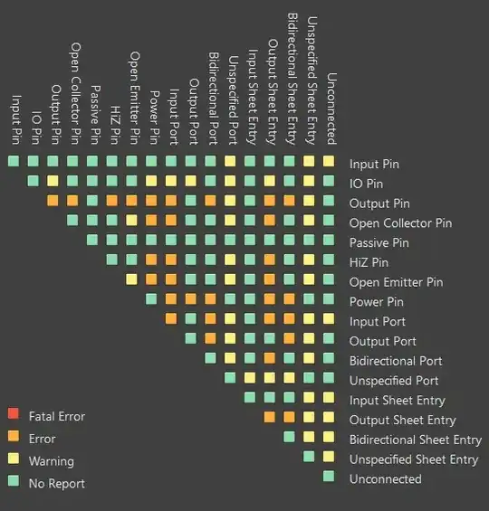
I have worked on both flat and hierarchical designs but will keep to flat designs where we just want connections from page to page. If we look at the Altium connection matrix, we see the basic rule allow input to output ports, output to output ports, but flags input to input ports:
This makes sense as a wire where it might be point to point with an input and output, or point to multi-point with one input and multiple outputs. So when we look at three ports like below and Altium flags a DRC error where the net contains multiple similar objects:
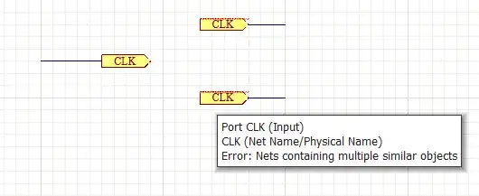
It is saying when you connect the ports together with an imaginary wire, there will be two drivers (inputs) that can cause contention and you, the designer, needs to resolve that decision. When the port types are flipped, Altium is satisfied a contention is unlikely:

It is pretty straight forward to use ports once we have this context in mind. The bi-directional and unspecified types are just another choice to make based on what the group of ports are suppose to do as an imaginary wire. This gets us to the graphical symbol of a port which I think is what confuses some people including me. Which way the port points appears at odds to the intent. The two outputs on the right looks more like when we intend a signal to go off page while the input looks like the signal is continuing from the port to the wire. But that's not the right context and the symbol shape is technically irrelevant. (1)
Some recommend bypassing or disabling DRC rules to make ports work but I don't believe it to be a good general rule. The job of DRC (Design Rules Check) is to help the designer catch potential errors, it is not the smartest system but that is why DRC exceptions is an option when reviewing DRCs. In this case, using the tool/rules as intended does serve to clearly communicate your design with others that share the same rules.
Finally, I do think the best way to avoid all this is to use off-page connectors that really don't care which way the signals are going. While you have to use ports in hierarchical blocks and spend the time to set types correctly, off-page connectors can still save time in a flat or mixed design.
(1) All ECAD tools give you enough rope to hang yourself in the name of personalizing the workflow. In Altium, you could just invert the connection matrix rules and flip the context of the port so now output to output is a DRC error and input to input is okay! But then personal preference start to conflict with a standard way to clearly communicate intent which is what a schematic intends to do.


