If it is for heating I guess AC is as good as DC. I would construct a toroidal transformer with just 1 secondary winding (depending on input voltage). To achieve the high current place several secondary windings in parallel, and make sure their wire length is exactly the same.
edit
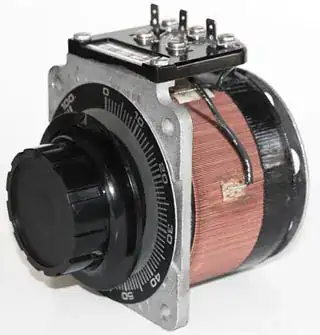
You can make to output voltage/current variable by feeding the transformer's input from a variac:
edit 2 (re your digital regulation)
I've been thinking about this for a while and I think the best idea is not having to switch the high current in the first place. Any other components than the metal strips themselves and the connections to them will cause losses of hundreds of Watts at least.
Maybe we still can use our transformer, and do the switching on the primary side, then we won't have to worry about sub-milliohm transition resistances. I would use a DC voltage on the transformer's primary, chopped by a MOSFET. The duty cycle will determine the secondary's current.
edit 3 (merge with other answer upon KV's suggestion)
First thing to make a note of is the vacuum. It means that all cooling will have to go through conduction through the wall of your vacuum chamber, since your temperatures won't be high enough to lose much heat through radiation, and of course there's no convection in a vacuum. This is also an issue for the heat dissipated in the load (the metal foil).
Going from 12V DC is a tall order. The standard way to go from a higher voltage and lower current to a lower voltage at higher current is of course an SMPS. Even at a low-ish 66% efficiency the 12V supply would only need to deliver 6.25A (for 75W). Piece of cake, it seems. However, the coil current is in the range of the output current, with peaks going higher. There are power coils which can handle 100A, but these have such low inductance that they need very fast switching, which causes very high switching losses in the MOSFETs. And then there's also the power lost as radiation, which may be a lot. Normal Schottly diodes are also out, so you'll need synchronous rectification using MOSFETs.
Talking about synchronous rectification: this is also an option for an AC power supply. You'll have a few voltage drops, however low, so you'll have to start with a voltage a bit higher than the 0.1V. The efficiency won't be high either, though even an extra 100mV drop will cause only 50W loss, so I think this is acceptable.
A classic diode rectifier is out due to the high power losses, and that's where the synchronous rectification comes in. You'll get a rectified sine, which is the closest you'll get to a proper DC source. (Don't even think about capacitors to smooth 500A currents!)
To measure the current you can use a couple of these sense resistors from Isabellenhütte.
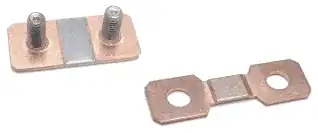
(Despite several parasitic voltage drops neither of those is suitable for current measurement since we have no control over the resistances involved.) The 0.1m\$\Omega\$ current sense resistor is specified for 200A, so you'll need a number of them in parallel.
The power in the resistors is low, they're specified at 5W maximum, but count on a multiple of that for parasitic resistances. Best would be to weld as much as possible, and mount on a metal wall of your vacuum chamber.
If you use three 0.1m\$\Omega\$ resistors in parallel theoretically you'll have 17mV at 500A. That's not much, but in practice the value may be higher, like 25 or 30mV, due to parasitic resistances. At 100A that will be 5 to 6mV. An instrumentation amplifier will help you bring this to a level which is easier for the PWM chopper to work with.
The rest is in the feedback regulator, which is actually a class D amplifier, after the measured current is averaged by a low-pass filter.
Don't use a too high chopping frequency; it will only increase the switching dissipation in the MOSFETs, and besides heat is slow, so you won't need sub-millisecond switching.
Plumbing: You'll need a battery of parallel MOSFETs, which I would solder as much as possible on copper bars, to reduce parasitic resistances as much as possible.