It's fundamental control and feedback theory. Thank you Mr Lyapunov, Mr Black, and Mr Nyquist.
Consider that everyone everywhere always wants the output of their power supply to have just the right voltage, no matter what. How to manage that? The best way we know of is by using feedback.
Feeding a sample of the output voltage, and current, back around to compare against some reference standard. Since the feedback is negative, or since the difference is take between the output quantity and the reference, an error signal is obtained.
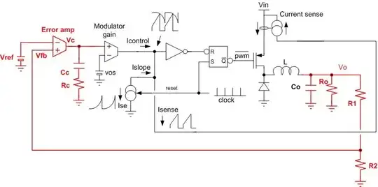
In your example circuit, the difference between Vref and Vfb is taken in the Error Amp to get Verr. For best accuracy, Verr needs be minimized, so the Error amp also applies gain, a lot of gain, the more the better.
It's kind of like the virtual ground situation with an OpAmp. The OpAmp has lots of gain, it's output is fed back to the input in a negative way, and the difference between the positive input and negative input becomes virtually zero. If the OpAmp is ideal with infinite gain the difference between the inputs is zero. Same basic idea with a PWM controller, although with extra stages. According to this idea, you just need infinite gain and bandwidth in the error amp (and everything else) to achieve what everyone everywhere wants all the time.
Infinite Bandwidth? Stop Here
If all the stages of the loop had infinite bandwidth, that would be all there would be to this. No compensation would be needed. But, there are bandwidth limits everywhere.
First, there is the Nyquist frequency of the PWM sampling. Because of sampling once per PWM period the gain and phase of the power modulator, all that stuff in your diagram between the Error amp output and the output filter input, will crash like a load of bricks going over a cliff at the Nyquist frequency.
Then because the switching power supply functions by time sampling various voltages, at least Vin and Vin Rtn, it's raw output is kind of bumpy and get's filtered to be smoothed out. The filter always provides at least 2, sometimes more, and usually complex poles. (Some would say that current mode control gets ride of one of the poles, but really it just gets move out so that you don't really much care about it.) Two plus poles provide 180 Degrees of phase loss, which with the negative feedback and lots of gain will make a wonderful oscillator.
We still need lots of loop gain especially at low frequencies to take care of output error and mains ripple, but how to handle all that phase shift as frequency goes up? Make an integrator of the loop. That way gain is maximally high at DC, but falls off by 20dB per decade, only adding 90 degrees of phase shift at the higher frequencies. Eventually, more poles show up, so loop gain is adjusted to have overall gain less than 0dB by then.
Most of what it takes to turn the loop into an integrator is done by the Error amp and it's compensation. The most simple case will have compensation for a single pole, a form of which is in your diagram with \$R_c\$ and \$C_c\$. This sort of compensation works pretty well for loops with current mode control and discontinous Flybacks, which will have a dominant pole at the output filter cap and load (\$f\$~\$\frac{1}{2\pi R_o C_o}\$). In this case \$R_c\$ and \$C_c\$ are chosen to cover that pole, and to set the Error amp gain to cross 0dB before any other poles show up.
This is rarely done by trial and error, as there are an infinite number of ways to mess up the loop and only a few ways to get it really right.
You should also know that the referenced diagram is a special, but favorite case. The error amp isn't really an OpAmp, but rather a transconductance amp, converting voltage to current. That's why \$R_c\$ and \$C_c\$ are shown going to ground instead of the inverting input. Vc ends up being the Error amp output current times the impedance of \$R_c\$ and \$C_c\$. It's a favorite case because transconductance amps are easier to make in an IC, so they are very commonly used in PWM controllers.
There are questions on this site that are related, here are a couple:
conditional-stability
Control Theory Boost Converter
Here's one from TI about Compensation amps.