3

I've got a small DC brushless motor for which I would like to set a current limiting circuit as a protection against over-current.

I thought I could pull it off with a simple fuse (or those current limiting fuse-like chips) but I can't. The fuse would only work to protect against short circuits because I want to set my limit just 20% (max!) above the nominal current draw of the motor.

I didn't design the motor electronics, and my competence in electronics is not great but I was basically wondering if I could use a circuit similar to those:

Schematic Schematic
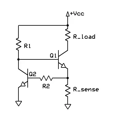
(source: wikimedia.org)

and if so how I would select the correct components (like transistors and resistors)?

The nominal current draw for the motor is 1.5A. I'd like the circuit to cut the power off when the current is 1.8A or more.

The reason I need something like this is because the load on the motor can vary greatly and would sometimes bring the current draw to 1.8A and more (which I consider unsafe - it's very subjective but that's what I'd like to do...)

Any idea?

edit: clarification: I want to switch power off when the current exceeds a certain value, which has to be about 20% max higher than the nominal power draw of my motor.

edit: how about that second schematic?

Glorfindel
  • 1,245
  • 3
  • 15
  • 20
user3617652
  • 31
  • 1
  • 3
  • You're combining two concepts here that aren't the same thing. Sounds like you want something that will act like a breaker if the current gets too high. But you use "current limiter" in your question title. A current limiter is typically a circuit that reduces the voltage as necessary to prevent the current from going above a preset value. In other words, it doesn't cut off the current, it just clamps it. Which one do you want? – Dan Laks Jul 29 '14 at 21:33
  • Tried a 1.1A PTC yet? – Ignacio Vazquez-Abrams Jul 29 '14 at 21:39
  • Hi Dan, you're correct. I want to cut off power all together when the current exceeds a certain value. is it possible to do this without a fuse or similar chip? I can't afford to choose a fuse with a value too close to my nominal current draw as it could over time (say days of operation) get it to trigger. I have playing with PTC's of different values, and to be able NOT TO trigger I need a value that is way higher than my nominal current, which will only be efficient against shorts. I've seen PTC's triggers after 8 hours of test. – user3617652 Jul 29 '14 at 21:58
  • Maybe you need a shunt, relay, and MCU then. – Ignacio Vazquez-Abrams Jul 29 '14 at 22:12
  • what about the second schematic, also found on the same wikipedia page.. – user3617652 Jul 29 '14 at 22:30
  • That schematic is a good start. However, as noted above, this will just regulate the current at its limit rather than cut power altogether. One option is to add hysteresis to the above circuit, so that current limit will stay engaged until the current falls below another threshold. What is the desired behavior when the current goes above the limit value? – user49628 Jul 29 '14 at 23:41
  • The first one was OK, I've done a similar thing, used Vbe and a resistor to turn off a pass element, I used a FET as the pass element rather than a BJT, but same idea. It doesn't really shut down, but just limits the current, which may be what you want. – George Herold Jul 30 '14 at 00:51
  • thanks for the comments. When it goes above that value (say 1.8A) I really need to turn the motor off for safety reasons. Limiting the current to 1.8A would not be safe in this application. The behavior of the PTC's I tried is really perfect other than for the fact I can't deal with the Current/Time dependence. If I could find a PTC that would NEVER trigger below 1.8A (no matter how much time it runs at that current) and that would ALWAYS trigger within say 10s after 3A, I would be happy. but no luck so far – user3617652 Jul 30 '14 at 01:47
  • OK then I think you need a comparator to SR flip-flop or something digital. – George Herold Jul 30 '14 at 01:57
  • thanks George, can you give me a description I could use to make a search about comparators SR flip-flop? I have no idea what you're referring to. thanks – user3617652 Jul 30 '14 at 02:10

1 Answers1

4

Your first circuit appears to be a current limiter. If the resistor values are properly chosen, the circuit will clamp the collector current (the current through the transistor and thus your load) at some value. It will not cut power.

The second circuit image you posted is not a complete circuit. The box labelled "Drive Circuit" represents some logic block that you would have to design. It takes feedback and directly turns power on and off to the load. That could be done any number of ways.

If you want something that acts more like a fuse that can be easily reset, something like a latching relay in series with the load could work. I'd probably use a comparator to trigger the relay when the voltage across a shunt resistor went above a threshold.

schematic

simulate this circuit – Schematic created using CircuitLab

The relay is a latching type. Rshunt is an appropriately chosen shunt resistor. R1 and R2 are chosen such that they divide to the voltage that triggers the comparator when the current through the load is 1.5A or higher: Vtrigger = 1.5A * Rshunt = Vcc * R2/(R1+R2)

Here are some considerations:
1. Rshunt should be small so it does not steal too much power from the drive circuit.
2. This circuit assumes Vcc is a stable voltage source. If it's weak and changes voltage under load, the comparator circuit will not trigger correctly.
3. If you're driving a motor, there might be a temporary current surge on start up that exceeds 1.5A for a short period of time. If that's allowable, you may need to build a low-pass filter into the non-inverting input of the comparator.
4. If you choose a double-coil latching relay (not shown), you can rig a button up to the second coil to reset the relay after it triggers.
5. The coil of the relay may not be compatible with Vcc.

Dan Laks
  • 8,584
  • 4
  • 27
  • 43
  • "Vcc" seems strange to use as notation here. – Ignacio Vazquez-Abrams Jul 30 '14 at 19:59
  • @Ignacio - just staying consistent with the circuits in the OP's question. I had originally used a voltage source in CircuitLab. – Dan Laks Jul 30 '14 at 20:18
  • Thank you very much Dan, it looks like it will do exactly what I need. My power source is a stable 12V DC PSU, voltage fluctuations do not exceed 2-3%. I am going to build this and use a pot to figure out the correct value for the resistor. a 5W 0.1 Ohm shunt should do the trick for Rshunt. Do you have any recommendation on the comparator I should use? thanks again! – user3617652 Jul 30 '14 at 21:58
  • Oh and I am awaiting a larger shunt to measure the inrush current of the motor on an oscilloscope. I suspect it'll be fine as it has PWM control and it features a nice/slow ramp in speed at startup. thanks again – user3617652 Jul 30 '14 at 22:00
  • No specific recommendation for a comparator. Just make sure its input offset voltage is much much smaller than the input signal from the shunt. Also, use high-precision resistors to make the divider. And make sure the Vgs of the MOSFET is compatible with the output of the comparator (i.e., when the comparator swings high, its voltage is high enough to turn on the MOSFET). – Dan Laks Jul 30 '14 at 22:59