1

I haven't seen this issue ever explicitly discussed.

Briefly, reflections cannot be avoided in a quarter wave transformer due to the characteristic impedance not matching the source or the load. In the resting state, one a frequency has been applied for a certain period of the, the full matched power will always be being transferred to the load.

What happens though when a symbol is received with different frequencies and phases. It's not like there's a training sequence for the exact frequencies and phases in an upcoming symbol in OFDM.. Oh yes, the cyclical prefix maybe. I haven't seen that particular benefit of a cyclical prefix be mentioned though.

There has to be a period of time where each frequency 'gets up and running', the first few periods will have slowly increasing power until you get the full power. If the symbol only contains one period then the power received would be different to the other frequencies, and the cyclical prefix isn't long enough to combat that.

Is it equalised out by taking into consideration the impulse response of the quarter wave transformer as part of the channel?

Lewis Kelsey
  • 259
  • 2
  • 12
  • 1
    I have multiple degrees in electrical engineering and was a ham-radio operator back in 1968 until the mid 70s. I know what a quarter-wavelength antenna is and I know what a transformer is. But I don't know what a quarter-wavelength transformer is. Can you explain that to me? I do have a concept of impedance matching in antennae and how it's done with stubs. – robert bristow-johnson Dec 27 '21 at 06:19
  • Lewis, there's multiple things that could be called a quarter-wave transformer, but none of them inherently "guarantee" a mismatch on both ends. In fact whatever you design, if it's not matched, you've probably done something wrong. – Marcus Müller Dec 27 '21 at 13:07
  • Anyway, the rest of the question makes no sense, because the whole point of OFDM is that it's a mechanism to counter multipath propagation ("echo") effects. That's its job. If you have an OFDM system built for the delay spread introduced by any part of your system, it will deal with it. That's how it's built. OFDM systems are equalizers in effect – take a non-flat channel, and use it as if it was flat. – Marcus Müller Dec 27 '21 at 13:08
  • (@robertbristow-johnson : what is usually meant with that term is that you take your transmission line of some characteristic impedance $Z_0$; your wave travels along that line happily, and all that happens to it that experiences a phase shift proportional to frequency times distance traveled. Now,you take some impedance, and add it after a quarter wavelength of transmission line. Effectively, that "$\lambda/4$ transmission line + load" element now looks like a $\pi$-phase-shifted version of the load (wave travels $\lambda/4$ forth and back). Can transform e.g. a 0° short end to a 180° open) – Marcus Müller Dec 27 '21 at 13:14
  • back in my day, we used to call that a "stub", i thought. – robert bristow-johnson Dec 27 '21 at 15:35
  • @robertbristow-johnson this whole question arose from my confusion as to why you need impedance matching, as opposed to impedance bridging, in a receiver LNA and ADC. The common stated reason is that it's to prevent reflections (which don't matter in audio applications, because it is too low frequency for the reflections to matter) which of course will distort the signal, not just power loss, but then I've seen antennas with a 1/4 wave impedance transformer for impedance matching, but this only matches for the steady state.. there are still transient reflections that distort the signal – Lewis Kelsey Jan 09 '22 at 17:24
  • So no I don't get why you have to transfer the maximum power because I did a quick calculation and it seems to me that when you do impedance matching, the Johnson nyquist noise power compared to the signal power is not as big of an SNR as the SNR derived from the signal voltage squared to noise voltage squared ratio when impedance bridging. I'd probably have to experiment on real equipment to see what the answer is – Lewis Kelsey Jan 09 '22 at 17:32
  • @LewisKelsey a BIG reason for matching is not having reflections between relatively large cable or trasmission line delays-- A long reflected delay added to a signal creates in band frequency ripple, and deep nulls if the reflections are loud (such as frequency selective fading). This isn't good and is the primary reason we want to ensure components are reasonably well matched in the transmission path. – Dan Boschen Jan 10 '22 at 06:21
  • @DanBoschen without matching the transmission line, even in the steady state there would also be a significant non flat phase and amplitude change I suppose for most of the frequencies (and in the case of using a 1/4 wave transformer, the frequencies outside the band of interest) – Lewis Kelsey Jan 10 '22 at 16:00
  • @LewisKelsey Only if there are multiple reflections with delay in between, and the delay is significant enough to create variation across the band. It is in effect the as multipath fading and the relationship of delay spread to flat or frequency selective fading. A single reflection other than raw power loss has no consequence to signal integrity. Consider high speed digital circuits with a series term at the source only (and big reflection at the load!)-- in that case the load reflects in phase and creates a perfect signal right at the load as long as there are no other reflections. – Dan Boschen Jan 10 '22 at 16:16
  • @DanBoschen the main question I have now is why you need to transfer maximum power to an LNA and ADC, and not just the voltage signal, someone asked it here but got no real answer (https://www.edaboard.com/threads/power-amplifier-vs-voltage-amplifier.29869/). Bearing in mind that by matching you'd surely also be transferring maximum Johnson nyquist noise power as well as maximum signal power, so I'm not seeing the benefit, particularly as it's ultimately going to be quantised as a voltage signal and power will ultimately be just voltage dependent I.e. $V^2$ – Lewis Kelsey Jan 19 '22 at 00:38
  • @LewisKelsey that is a good other question to ask- best on the electronics site as it is related more to that – Dan Boschen Jan 19 '22 at 00:46
  • @DanBoschen I had to do it myself, but I think I've proven that SNR is max when it is matched.. https://electronics.stackexchange.com/a/606659/199862 also, I will get to that $N_0/2$ notation issue question you commented about soon – Lewis Kelsey Feb 01 '22 at 18:18
  • @LewisKelsey Ah I didn’t see that before— I have a good answer for you as soon as I free up some time that I will add there if someone else doesn’t first. It has to do with Johnson current and voltage noise and why we use certain impedances for the components and transmission lines at RF . – Dan Boschen Feb 01 '22 at 18:53
  • @DanBoschen I think I got the numbers wrong on that one because I was still using the time domain RMS of the voltage signal, I think the expected noise amplitude at a specific frequency is $\sqrt{4kTR}$ I believe – Lewis Kelsey Feb 01 '22 at 20:16
  • 1
    @LewisKelsey no that is the noise density per sqrt {Hz} at the source as sqrt{4kTBR} for a given BW but the most you can get out is with a matched load R which ends up being kTB as a power quantity (independent of R). I will detail and answer there — so we don’t annoy the chatter gods, please hold off on further comments until you see the answer (and you can comment there) – Dan Boschen Feb 01 '22 at 21:49

3 Answers3

3

The OP clarified in comments that his real question/concern is with the transient response of the reflections that occur in a 1/4 wavelength transformer. In any typical application given the relatively high carrier frequency, meaning short wavelength, in comparison to the much longer symbol duration times, this transient would be of no consequence. Yet this is an interesting link between a common microwave component and signal processing, so I will explain further how this all ties together and can be modeled as a IIR filter to predict samples of the transient response in question. This will also help to quantify at what modulation bandwidth we would actually start to care about something like this.

Yes this is a signal processing answer, please read on!

First I will introduce some basics with 1/4 wave transformers sufficient to explain the signal processing. A quarter wave transformer is a relatively narrow band device that will match impedances (traditionally used in a microwave circuit). When the load impedance matches the source impedance we get maximum power transfer, and the 1/4 wave transformer will provide for such an equivalent match between a mismatched load and source. Specifically the 1/4 wave transformer is 1/4 wave at the center frequency of operation (and thus presents a 90° phase shift to the center frequency of operation, or $e^{-j\pi/2} = -j$ to propagate from one interface in the transformer to the other). In order to provide a perfect match between source and load impedance, the impedance of the quarter wave transformer must be the geometric mean. For example, to match a 200 ohm load to a 50 ohm source, the impedance for the transformer would be $Z_o = \sqrt{(50)(200)} = 100$ ohms.

Finally the reflection coefficient based on any mismatch is given by:

$$\Gamma = \frac{Z_L-Z_o}{Z_L+Z_o}$$

Which describes the magnitude (such as a voltage quantity) and phase of the waveform that would be reflected back at that interface. For example, as depicted in the diagram below, when the wave-front from the Source first meets the transformer, the reflection coefficient will be $(100-50)/(100+50)=+1/3$, so $1/3$ of the incident voltage will be reflected back toward the source (from this very first reflection in time, which is depicted by the arrows moving diagonally to the right; not depicted, but all subsequent reflections, eventually, will actually cancel this first reflection completely such that in the end the interface appears to be perfectly matched). Similarly some of the subsequent reflections are inverted 180°, such as when the wave-front that reflects back from the 100 ohm to 200 ohm interface (which also is +1/3) comes back and then is an interface going from 100 ohms to 50 ohms. In this case the reflection coefficient here is $(50-100)/(50+100)= -1/3$. $\beta$ is the transmission coefficient such that the total power between reflected and transmitted is equal to 1 ($\Gamma^2+\beta^2=1$)

quarter wave transformer

Further, the wave will take time to transition the transformer from the Source Interface to the Load Interface, and this time delay is carefully determined to be a quarter wavelength or 90° at the center frequency of operation. Thus we see in the diagram above how first $\beta$ transitions the first interface from Source to Transformer, but becomes $-j\beta$ by the time it reaches the Load interface. The ratio of transformer to load impedance is the same to cause a reflection of +1/3, and thus we get $-j\beta\gamma$ as the complete internal reflection up to this point. More importantly with regards to overall transmission, we see how the first occurence of a transmitted waveform in time is $-j\beta^2$, and then after the time duration of back and forth in the transformer, we get an additional $-j\beta^2\gamma^2$ which will coherently add, and then again after another back and forth we will get an additional $-j\beta^2\gamma^4$, and so on as an infinite series.

OK, here comes some signal processing!

We have the case of an infinite series and specifically waveforms that add after integer increments in time which is a perfect opportunity to use the z-transform! Just as the z-transform eliminates all those exponentials in the Laplace Transform to give us simple polynomial forms, we can eliminate all the exponentials that could optionally be used to proceed with what I am about to show.

Similar to an FIR filter structure, the resulting output can be described as:

$$H(z) = -j\beta^2 -j\beta^2\Gamma^2z^{-1}-j\beta^2\Gamma^4z^{-2} + \ldots$$

Except of course as an FIR filter it would go on forever (which as we'll see is an IIR filter) Factoring out the common $-j\beta^2$ and expressing the rest as a summation we get:

$$H(z) = -j\beta^2(1 + \Gamma^2z^{-1}+ \Gamma^4z^{-2} + + \Gamma^6z^{-3} + \ldots$$

$$ = -j\beta^2 \sum_{n=0}^\infty \Gamma^{2n}z^{-n}$$

$$ = \frac{-j\beta^2}{1 - \Gamma^2z^{-1}}$$

We see that the summation converges to unity transmission (with a 90° phase shift), but also this is the transfer function for the equivalent IIR filter. From this, using practical numbers for the back and forth delay within the transformer given by $z^{-1}$ we can determine the equivalent analytic signal impulse response for the 1/4 wave transformer structure (meaning the lowpass equivalent impulse response relative to the center operating frequency).

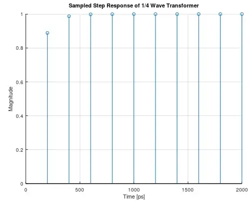
As detailed further below, a reasonable delay in implementation could be as long as 100 ps if implemented at 2 GHz as a microstrip trace on a circuit board. Doubling this for the round-trip delay associated with $z^{-1}$ would be 200 ps, or similar to a sampling rate of $1/200E-12= 100$ GHz (and we start to get a hint of why this won't effect an OFDM signal, at least the ones we use today). In the plot below is the resulting impulse response (or samples on the continuous time impulse response that would actually occur) for the example quarter wave transformer. As mentioned in the closing paragraph below, this is significantly faster than the coherence time of any OFDM waveform, such that the quarter wave transformer will certainly settle under condition of any dynamic transient conditions much faster than the transition time in the waveform. If the waveform was wideband enough for this to matter, this also would not be a functional matching structure since it is a relatively narrowband matching device (those bandwidth considerations are detailed further below in my original answer).

impulse response

Step Response

prior answer:


The 1/4 wavelength transformer is used in the RF path of the signal which in this case would be a relatively narrow bandwidth compared to the carrier, as far as considerations for 1/4 wavelength transformers go. This means (to bottom line it) there is little consideration on the spectral effects of the quarter wave transformer over the expected bandwidth of interest. I detail this further below.

The formulas for the quarter wave transformer that relate reflection coefficient and insertion loss to bandwidth relative to the perfect match at center frequency $f_o$ are given below and referenced here:

$$|\Gamma| = \frac{1}{\sqrt{1+\frac{4Z_o Z_L}{(Z_L-Z_o)^2}\cos(\pi f/(2 f_o))}}$$

Where:

$\Gamma$: Reflection coefficient (voltage reflected/voltage incident)

$Z_o$: Source impedance (or of first transmission line at input to transformer)

$Z_L$: Load impedance (or of second transmission line at output of transformer)

$f_o$: Center frequency where transformer provides perfect match ($\Gamma=0$)

$f/f_o$: Relative frequency related to center frequency

The insertion loss in dB is related to the reflection coefficient as follows:

$$S_{21} = 10\log_{10}(1-|\Gamma|^2)$$

I plotted these for two cases, a 2:1 mismatch and a 4:1 mismatch which provides us with an intuitive feel for how much we care about variation over frequency for practical examples such as OFDM carriers:

Reflection Coefficient

Insertion Loss

Consider a practical example with easy numbers of a 1/4 wavelength transformer matching a 50 ohm impedance to a 200 ohm impedance at 2 GHz. To properly implement this match, the transmission line would have an impedance equal to the geometric mean of the two impedances being matched or in this case 100 ohms. And with that for any signal components with a frequency exactly at 2 GHz, there would be no reflection and the incident wave would be fully delivered to the load (neglecting implementation losses). A wide OFDM channel is typically 20 MHz, but even if it was as wide as 100 MHz at this carrier, that would be a fractional bandwidth ($f/f_o$) of only 0.975 to 1.025. Even with this extreme mismatch (50 ohm to 200 ohm) we would see an insignificant loss and any distortion would be treated as flat fading (and very minor, and across the entire OFDM occupied bandwidth!), which would be of no concern whatsoever.

Further any temporal effects such as the impulse response of the transformer (which will occur as the initial reflections converge) will be unlikely to affect OFDM waveforms when comparing the inverse of the signal bandwidth to the propagation time for a typical quarter wave transformer at any given OFDM carrier where it would be practical to implement a transformer as a quarter-wave matching section. You could see this by determining the impulse response of the transformer (from each reflection converging) and then take the Fourier Transform to get the frequency response. The impulse response will manifest as an time constant with an effective bandwidth much wider than the modulated signal-- which means when the signal itself transitions, it can't transition fast enough to have the transient effect of the transformer to have any effect: by the time the signal has traversed a transition, the transformer will have long been settled. Consider in free space waves propagate at approx 3.3 ns/m (so ~ 2 ns/m on a circuit board) and what the distance would be for the particular carrier you have the 1/4 wave transformer at (which would only be practical to do above 2 GHz in most cases). So even as low as 2 GHz a 1/4 wave on a circuit board might be on the order of 0.5cm. This would take 106 ps to propagate from one end of the transformer to the other. Compare that to the coherence time of a 20 MHz OFDM waveform (~ 50 ns).

Dan Boschen
  • 50,942
  • 2
  • 57
  • 135
  • Yeah the issue is that when you match according to $Z_0^2= Z_LZ_{in}$ there is a series of transient reflections until it reaches a steady state, so eventually after the incident wave has bounced back and forth, the sum converges at $\Gamma =0$ but until that point there is a reduced power in the received waveform, that's what I was referring to, and if this is an issue it is then also tied to my other question https://dsp.stackexchange.com/questions/80755/how-are-the-reflections-in-a-quarter-wavelength-transformer-dealt-with-in-signal/80815#comment169717_80755 – Lewis Kelsey Jan 09 '22 at 21:58
  • @Lewis Isn't it a non-issue since the transition time is so much faster than the inverse of the bandwidth? - Consider in free space waves propagate at approx 3.3 ns/m (so ~ 2 ns/m on a circuit board) and what the distance would be for the particular carrier you have the 1/4 wave transformer at (which would only be practical to do above 2 GHz in most cases. So even as low as 2GHz 1/4 wave on a circuit board might be on the order of 0.5cm. So 106 ps to propagate from one end of the transformer to the other. – Dan Boschen Jan 09 '22 at 22:10
  • (I think you linked this same question?) – Dan Boschen Jan 09 '22 at 22:11
  • but the quarter wavelength transformer is the length of 1/4 wavelength of that frequency, so it is a transmission line or distributed circuit element, so I mean it would take a few wavelengths of the signal to be received until it reaches a steady state right, and no I linked the comment on my question. I suppose that at that high of a frequency it would be such a small portion of a few microsecond symbol, so it wouldn't matter that much? – Lewis Kelsey Jan 09 '22 at 22:27
  • Yes- that is a few wavelengths of the carrier frequency--- think of how many cycles of the carrier would be in any given symbol of your OFDM waveform (very many!!!) – Dan Boschen Jan 09 '22 at 22:29
  • Got it, I edited my comment before you replied. I was wrongly thinking about the baseband signal instead – Lewis Kelsey Jan 09 '22 at 22:30
  • @LewisKelsey I detailed the actual transient behavior; please check if that makes sense to you. – Dan Boschen Jan 10 '22 at 06:13
  • The impulse response would be the derivative of the DC step response, so a chain of impulses, but I can't find a frequency response diagram anywhere there's probably something that can be done in matlab but I've never got into the way of using matlab, the only diagram I can find is reflection coefficient vs frequency or steady state frequency response, anyway my guess is that the delay spread of these particular reflections fits the signal within the coherence bandwidth in this case. I'll try to compute the frequency response tomorrow – Lewis Kelsey Jan 10 '22 at 06:19
  • Consider a step response as the integral of the impulse response-- this means if your waveform suddenly stepped (worst case transient) the transformer would follow that step in less than 1 ns (add up those impulses). 10%/90% Rise time is approx 0.35/BW, so if something were to have that fast of a rise time, it would need to have a BW higher than 350 MHz. Since no OFDM waveforms (today) are that wide, that means they will all rise slower than than in a dynamic transition. – Dan Boschen Jan 10 '22 at 06:26
  • I created the frequency response (https://www.desmos.com/calculator/ul59lvqd4s) for the quarter wavelength of 2.4GHz with source impedance 20 ohms transformer impedance 50 ohms load impedance 125 ohms, you can see that when it's matched (which it will be at 2.4GHz), there is an imaginary 1.75 and real 0, this represents the 90 degree phase shift that occurs, and 1V (50/(50+20)) = 0.714285714V; 1.75*0.714285714V= 1.25, which is the voltage that you need over the load to achieve the same power as the power dissipated in the source – Lewis Kelsey Jan 16 '22 at 18:57
  • @LewisKelsey nice- if you matched it properly the impedance of the transformer should be the square root of the product of your source and load impedance (which causes the reflections to all add and cancel properly since the same ratio is maintained at each Interface). You can also make wider bandwidth transformers by cascading two or more sections with gradually increasing impedance (at the complexity of more board area) – Dan Boschen Jan 16 '22 at 19:31
0

Usually, you'd add such elements with the express intent of matching something – e.g. you need to add some $(10+2j)$Ω lossy inductance to match A to B, but for physical reasons, a capacitor is easier.

So you build one, and attach it in a way that shifts things around. Now, bear in mind all these delays are in the order of one carrier wave period – and that's the whole point: to the baseband system, the effect looks like a complex impedance, i.e. the channel gets multiplied by a complex number. (if you're sitting in front of a Smith chart: that's what moving around in that plane is)

So, if your channel was flat before, it's flat after. It's still represented by a complex number, not by a spread-out impulse response as far as the baseband system (e.g. OFDM) is concerned. Otherwise, your matching techniques weren't "wideband" enough.

Even if your system ends up being frequency-selective within your baseband bandwidth, then: it's OFDM. It's designed to deal with frequency-selective channels, so your confusion about how the channel is sounded and compensated is a general confusion about OFDM, and has little to do with your microwave engineering question here.

Marcus Müller
  • 30,525
  • 4
  • 34
  • 58
0

First, a quarter-wave transformer is an RF thing, and RF generally assumes that the bandwidth of the signal being dealt with fits nicely into the bandwidths of the receiver and the transmitter. If you're designing a system where the transmitted bandwidth is such a high percentage of the total bandwidth that a filter in the signal processing chain doesn't appear flat across the bandwidth of the signal, then you should subject that filter to enhanced scrutiny during the circuit design.

Second, the whole point of OFDM is that it avoids intersymbol interference by splitting the signal up into a whole bunch of narrow-band, long-duration signals. When you do have some filtering in the signal chain (whether it's in the transmitter, receiver, or the transmission medium), OFDM increases the chances that an individual signal will "see" a spectrally "flat" channel, at the cost of the possibility that each individual signal's amplitude and phase may be different from others in the constellation.

This is an advantage when you have a channel that you cannot control but that contains multiple path. In the time domain, multipath can cause fairly long-period intersymbol interference that is difficult to equalize. In the frequency domain, multipath causes phase changes and nulls -- both of which can be handled by OFDM, if it's wrapped with the right error correction.

Your quarter-wave transformer with reflections, if it's bandwidth intersected with the bandwidth of your OFDM signal at all, would just appear as multipath.

TimWescott
  • 12,704
  • 1
  • 11
  • 25