2

I'd like to know if anyone sees big issues with this system I want to implement in my home. The software is in beta, I will start doing the hardware side of things in a few weeks.


Current Home Status


  • almost all lights are temporary push-buttons connected to a 220V relay
  • two locations in the house where all the wires are connected

Since an image is worth a thousand words... (the items there are example, not the real ones I will use (different 220V relay, Arduino-connected relay but the main idea is well represented) diy system


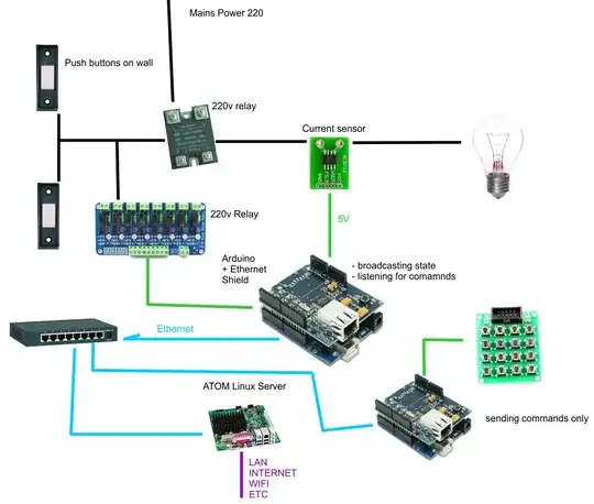
  • adding a 220V relay in series with the normal light switches, connecting it to an Arduino
  • a 30 amp current sensor is used for detecting the state of the light switch
  • each Arduino (or at least one in a pack of many Arduinos - where one won't be enough) Ethernet shield is used to send/receive data over a closed network (not accessible from LAN/internet)
  • a mini-itx atom board running Linux and some node.js software listens for UDP packets on the network (the controller)
  • each Arduino sends every x minutes the on/off state as a UDP packet
  • each Arduino send a UDP packet when the state changes
  • each Arduino listens for UDP packets addressed to it and can turn on/off a relay
  • the controller receives and stores all data on a network card, using a second for providing web interfaces with authentification for lan
  • other Arduino devices will be embedded in switches, sensor arrays, and can send UDP commands to turn on/off lights
  • the controller has event-driven and schedule-driven actions, state changes, and can send commands to the Arduino

Advantages

  • preserving the normal light switches in the house
  • if the system goes down the normal switches still work
  • modular - I can add more nodes as I need them
  • the controller is needed only for advanced operation
  • relative
  • future-proof - I can't imagine UDP protocol becoming obsolete anytime soon
  • secure web access from outside the home

Disadvantages

  • a lot of Arduinos and Ethernet shields might be needed

Optional items

  • Raspberry Pi's with thermal webcams to detect presence, using a modified zoneminder install to send UDP packets based occupancy
  • a couple of Android phones with broken GSM and weak batteries used as touch-screen interfaces inside the home
  • a Nokia phone used with Gammu to provide the ability to command the home via SMS

Clarification

The 220v relay that are set up right now were put into place to allow lights to be opened or closed from multiple places from a room. Think of the relay as a 3-sided control circuit

  • one side has the 220v mains coming in
  • one side has the push buttons that work on 220v
  • one side has the output to the light bulb

The 220v is an on/off relay. Each time any button is pushed, it toggles it's state, as long as you press a button more than 0.1 seconds (so it said in the relay manual).

My electrician installed the 220v relay, it is not 'normally open' or 'normally closed'. If powers goes down and then comes back the lights return to their previous states.

To trigger the 220v mains relay all i have to do is use a normally-open arduino-relay and trigger the closed state for more than 0.1 seconds. I just need to send a 220v "pulse" to the 220v relay. This is the main reason that the lights will still work as long as power is kepy. All the arduino can fail and the normal lights will work as usual, I will only lose the remote-controll posibility and advanced scheduling/scripting.

As for pricing I am sourcing arduino+ethernet or mega+ethernet (and a few other arduino replicas) at around 15-25$ per pair, so the cost is relatively low. In the main controller software I estimate 40 hours of work, and then a few hundreds of hours over a few years refining the user interface and adding events and so on.

All the items will be placed in 2 boxes inside the house, one for each floor, and a third box will be controlling the garden,patio and watering.

--- Later edit --- Built the schematic, you can see it in action on youtube http://www.youtube.com/watch?v=BmsdXMbd2vo

vlad b.
  • 131
  • 2
  • 7
  • 2
    Why are your push buttons going to the relay and not the Arduino? Where are your normal wall switches in all of this? Have you looked into X10, you can still integrate that into an Arduino or PC and remove all your high voltage wiring. If you choose to buy relays, make sure they have a high amperage rating and duty cycle and realize you're powering an electromagnet to use the relay which is a power hog. – Jason Jun 21 '13 at 14:35
  • 1
    How do you intend to preserve existing switch function if the system is down AND still be able to have the system control on/off status? – gregmac Jun 21 '13 at 14:35
  • @gregmac We stated he's planning on wiring the relays in series, so using the NC (normally closed) would act as if the system wasn't installed. You can look at it as the added system would not be able to turn the lights on but rather be able to turn the light off or return them to their previous state. Still wondering where the normal switches are though because they would act more like a "turn off only" as well. – Jason Jun 21 '13 at 14:56
  • The only way I can think of is to use SPDT latching relays (which means you also need 2 I/O contacts to the controller for each) and for the 'normal' switches to all be 3 way switches, with the relay acting as the other 3-way switch ("3-way" == "2-way" if you're in the UK). This likely means replacing most switches and replacing existing wiring with 3-conductor wire. Anyway.. I can't fathom how this DIY approach can be cheaper than Insteon/UPB/Zwave (or X10, but don't use that, it's terrible). DIY the software/controller side, but not the hardware/switching. – gregmac Jun 21 '13 at 15:18
  • Added clarifications. @gregmac - I have to modify 2 things - connect the aruduino-relay to the 220v relay and splice the wires to the lightbulb and add the current sensor. – vlad b. Jun 21 '13 at 19:15
  • @Monso - the 220v relay is connected to the wall switches because the buttons work on 220v. – vlad b. Jun 21 '13 at 19:18
  • Can you share a reference for the 220VAC relays you're using? I haven't run across one that works the way you describe it where you just interupt the power to the light and the relay changes state. I can see how that might work if the relay is switched on, but if the relay is off, how does it know that you've flipped the switch? Or is there a separate 220VAC control channel that triggers the relay? – Johnny Jun 22 '13 at 00:41
  • The wall switches have the + terminal always connected. When i press it the 220v is sent to the relay. The relay then changes state and it appears it stops the current flow until i stop pressing the button. My electrician will come by in a few days and i will take one out of the junction - I usually avoid messing with 220v without him. The 220v relays are store-bought, nothing custom. – vlad b. Jun 22 '13 at 07:08
  • "where you just interupt the power to the light and the relay changes state" - It's actually the oposite. send 220v to the relay and it changes state. – vlad b. Jun 22 '13 at 07:42

2 Answers2

1

I've been doing something similar for the past couple of months. At present the setup only extends to my workshop (for testing). Currently I am using a single UNO for control which reads various sensor states, including light level and temperature/humidity, plus some door (reed relay) and IR movement sensors. The arduino reads the state and sends messages to some software ( currently Python 2.7 under Ubuntu) over UDP which then does the processing that is required and sends control commands back to the Arduino, again over UDP. The processing currently amounts to checking the internal light sensors and switching on the lights if necessary. Ultimately I want to migrate all my lighting to 12v LED so I can run off stored solar, but at present I am using a system similar to yours in that the relays are in series with the power switch for the lights, normally closed, so that if the control circuitry fails the light switches should operate as normal. I also have some external IR sensors and the same system activates an external security light, this time with a normally open relay. I consider using the normally closed relays as essential for the main lights, otherwise the domestic management will kick off once the system is rolled out to the rest of the house. I want to use LEDS because of their dimmable nature when using the PWM enabled pins of the Arduino, this will then enable a nice low level of light for those nocturnal toilet trips, all automatically of course. I have just taken delivery of a Mega 2560 which will provide a lot more IO. Like yourself I envisage having separate Arduino's for input and output. I am developing the control system in python, with the intention of migrating it to raspberry PI once development has finished. This will allow me to run it all an enclosure with a status screen hooked up to the composite video. I currently have a limited status screen running on the PC, which allows me to control the brightness of LED panels and GU16 bulbs. I have configured the arduino so it will accept commands from any device on the network, so I can set up some control from the android devices I have around the house. I also have a fully working zoneminder installation, but had not considered using it to trigger anything as yet, but then again I don't have any internal cameras on that, just external. I did consider thermal imaging, as you suggested, but I think cost is a major issues (would need to come in at below $100 Australian, per room to be feasible for me), so I'm persevering with low cost IR sensors (about $2 each from China). My Arduino code is not best but I am more than willing to share it. It is currently set up to monitor the various sensors in a constant loop, and also listens for a 3byte UDP string in the form of 410 (4 is light 4, 1 is for on, the last digit is used for a brightness level for the LED)

I do agree with the comment about the resale values of the house, but I'm not planning to move anytime in the foreseeable future. Your needs may be different.

The python code also does some DPMS control of the monitors in the workshop. Currently they are put to standby after 10 minutes of no workshop movement. I am in the process of setting up some power sockets that are switched in the same way as the lights, so the system can turn off things like my soldering iron and amplifiers that I frequently forget to leave on.

Let my know if I can be of any help with your project. It sounds great. Good luck

John

user13613
  • 11
  • 1
  • I'm learning / using node js for the main controller. You can take a look at my prototype here: https://github.com/vladbabii/MasterController-HomeAutomation . I think the best approach to this is an even-driven language that can handle multiple in/out packets and streams of data (tcp connection for continous stream of state, tcp connection for json-encodeded browser-useable data, udp commands listening and generation). The difference in what I'm doing electrically is that i have a 220v relay that is not NO or NC, it just switches state when it gets a pulse of 220v. – vlad b. Jun 23 '13 at 08:36
  • And my arduino-relays are normally-open and close for ~100ms to trigger a on-off state. Can you share more about how you structure your udp packets? I'm using the plain get structure: identifier=<current_identifier>&action=sensor_update&sensor=&value=. I'm not sure about going wireless vs pulling cables in some places. – vlad b. Jun 23 '13 at 08:40
  • I'm considering using two Raspberry Pi's as servers but I haven't figured out any way to do reliable fail-over and restarts when the main one crashes. Any ideas on this? – vlad b. Jun 23 '13 at 08:48
  • Hi Vlad, my UDP code is a hangover from an openCV project I was doing earlier on in the year (to track cats in my back garden), which used pan and tilt servos, so I was sending three byte strings to the servos to control their movement. – user13613 Jun 25 '13 at 23:11
  • I'm self taught and have never really got to grips with C, but never the less the code mostly works. As such I've done the absolute minimum I can get away with in the Arduino, most of the decision making (whether to turn lights on/off e.t.c.) is done in python, ultimately to run on the Pi. – user13613 Jun 25 '13 at 23:13
  • I'm not sure how best to post the code as it doesn't seem to fit in this window :) I'll send you a contact through your site and we can sort it from there. I do intend to have a blog about the project, but have yet to find the time. – user13613 Jun 25 '13 at 23:17
  • With the way the software has been split (the arduino doing the sensor readings and switching, and the Pi doing the logic), I see no reason why you couldn't have two Pi's running in parallel, with the same software, each sending packets to the arduino. As long as they are both doing the same thing the end result should be OK. The arduino doesn't care where it gets the data from as it's just monitoring its listening UDP port and doing something if it gets a three byte data packet. It also monitors the sensors but I am using the PIND and PINB registers for this (simultaneous reading). – user13613 Jun 25 '13 at 23:22
  • Using the registers is a little trickier, involving XORing it with it's previous state and then acting on the change, if any. It's nice and fast and does eight sensor simultaneously. The code is still very much in development and is not without some bugs, but I'm currently in the process of replacing the Uno with a Mega and taking the opportunity to tidy-up the experimental wiring. – user13613 Jun 25 '13 at 23:25
  • The biggest issues with having 2 servers that handle everything in parallel are timing and synchronizing the data. While the later can be achieved fairly easily, the first one is trickier on a PI since it does not have an internal clock so you end up doing very many time synchronizations. I'm still studying everything, will post back here when I'll have an answer. Also posted a question about this here: http://raspberrypi.stackexchange.com/questions/8125/multiple-raspberry-pi-web-servers-with-fail-over – vlad b. Jun 26 '13 at 06:32
0

The biggest drawback is the highly custom nature and the modifications needed when you go to sell your house.

If I was looking at buying a house today that someone had extensively modified to installed a totally custom DIY system in using "state of the art" from 10 or 15 years ago, I would probably be thinking along the lines of "wow, I have to rip everything out and completely redo the electrical in this house" and the price I would be willing to pay would reflect this. I'm being a bit extreme to illustrate the point, but you need to consider this.

gregmac
  • 29,050
  • 16
  • 86
  • 160
  • All i need to do is remove the current sensor and connect the wires back, and disconnect the arduino relay from the 220v relay. And then put back the old main cable junction covers instead of the ones i have now to hold all the extra stuff. – vlad b. Jun 21 '13 at 19:09
  • Or you can install off-the-shelf remote-controllable switches/dimmers, and never have to worry about disconnecting them or dealing with the house current at all. – keshlam Nov 30 '14 at 14:48