0

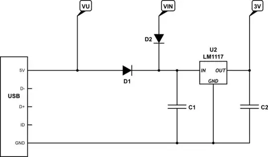
I read this answer https://arduino.stackexchange.com/a/51878 to a different, but related question. It seems like VIN on the NodeMCU is directly or via diode connected to the USB connector.

Image source: https://arduino.stackexchange.com/a/76119

I'm going to run my NodeMCU with a 5 V power supply connected to the USB connector. And I also need approximately 5 V for another part. So I was thinking of connecting it to VIN of the NodeMCU. So I don't want to power the NodeMCU from VIN, but I want to draw power from VIN for another part.

Is that a bad move or perfectly fine? And if it's okay, how do I find out the maximum current? Because I think the line from USB connector to VIN has some limits, so to not damage the board?

rattlesnake
  • 115
  • 1
  • 6
  • 1
    There is some unknown quantities here. NodeMCU made a couple of versions of the ESP8266 development board we all know and love. That was well documented and schematics are available. Then the Chinese took it and cloned it changing the schematic in the process, and called it the V3. But no one has published official schematics of it, and no one really knows how the diodes are actually connected on that board. I have just ordered one of them from Amazon to do a bit of reverse engineering on it to finally get a definitive answer. – Majenko Oct 01 '21 at 21:49
  • 1
    I'll post an answer on this thread, and possibly also write a blog post on my site about it with more detail if I think it's worth it. – Majenko Oct 02 '21 at 08:59

2 Answers2

2

You cannot power items from the VIN pin of the NodeMCU V3.

The power circuit is like this:

schematic

simulate this circuit – Schematic created using CircuitLab

As you can see no current can flow out of the VIN pin because of diode D2.

You could, though, draw current out of the VU pin, though (situated at the top left of the board when the text is normally oriented) which is directly connected to the USB port's 5V pin. How much current can you draw? Well, there's nothing in the circuit to limit it, so whatever the USB port that the board is connected to will provide (less enough to run the ESP8266 module).

If you want to draw 1A through the VU pin and the power supply is rated for 2A there should be no problem. The traces for the VU pin are reasonably chunky.

A better solution though would be to power the NodeMCU board and your external components through separate power feeds from the power supply - that way there can be no interference from the board.

Majenko
  • 105,095
  • 5
  • 79
  • 137
  • Huh... First of all: thanks for looking into it. However, second of all, I don't understand how this is possible. https://i.stack.imgur.com/6NKYn.png This is exactly how my board looks like. Maybe there are different NodeMCU v3? In your schematic, shouldn't I measure 0 V on VIN because it's against the diode direction? But when I connect USB and measure from VIN to GND pins, I read 5 V. (I get 5 V as well from VU to GND, by the way.) Again, thanks for you help :) – rattlesnake Oct 05 '21 at 13:24
  • The only way you can get power out of VIN is if the diode is faulty or installed backwards. That board is identical to the one I've torn down. I am half way through a full reverse engineering of the circuit at the moment. – Majenko Oct 05 '21 at 14:42
  • Hmm, no idea what to tell you. The board is basically new, I haven't done anything with it so far. I also read 2 to 3 ohm resistance between VIN and VU in both directions. I think if there would be a diode installed like in your schematic, that also shouldn't be the case. I cannot explain my readings. Is there anything I can do? Which part would be the diode in question? Maybe I can test something there? My equipment is very limited though. :( – rattlesnake Oct 05 '21 at 15:42
  • @rattlesnake If you have a DMM it should have a diode test mode. It should tell you the forward voltage of the diode. In one orientation it should give you abou 0.25V. In the other it should read open circuit. The diode in question is the one closest to the pins. If you're interested the copper traces can be viewed here: https://cloud.majenko.co.uk/index.php/s/ewCn6JmYdWWglRj The two diodes are in the bottom left - you can just make out the pads in silver above the bottom left mounting hole. You can see both the diodes connecting the power to the 5V rail - the lower one going right to left... – Majenko Oct 05 '21 at 15:52
  • ...from the USB power, the upper going left to right from the VIN pin. From there the 5V goes to the input of the LM1117 voltage regulator. – Majenko Oct 05 '21 at 15:53
  • Well, this is interesting. I do have a digital multimeter. However, it is a very cheap one. It does have a diode test program though. I have never used that before. Can I used it while the diodes are soldered onto the board? On the diode closer to VIN I read 233 in one direction and 1. in the other direction. (Not 1, but 1. which mean infinite for the resistor test program.) For the other diode closer to the edge, I measure 002 or 003 in both directions. So... no idea what that means, but it doesn't make any sense to me. – rattlesnake Oct 05 '21 at 16:13
  • With the diode near VIN which way round are the probes when you read 233? It should be red towards the outside and black towards the inside of the board. The other diode sounds broken or short circuited. 233 sounds correct though - 233mV is about the same as I measured and is typical for a small schottky diode. If you peer closely at the diodes you should see a stripe at one end, which is the cathode (where the black probe goes for it to read right). – Majenko Oct 05 '21 at 16:17
  • Yes, I can see the stripe with a magnifying lens: https://i.stack.imgur.com/5Adnr.jpg I hope the photo is good enough. I measure 233 with red left side (towards the outside) and black right side (towards the inside of the board). Isn't that what you said? – rattlesnake Oct 05 '21 at 16:56
  • @rattlesnake Yep, that's correct. That diode is working fine. You may be measuring 5V on VIN because there's no load and it's just floating. Maybe try powering something small from it and see if it works. The other diode, though, is short circuited. Either because the diode is dead (they usually fail short) or there is a defect in the PCB. – Majenko Oct 05 '21 at 17:07
  • I'm sorry to say but it seems like VIN does indeed work as an output: I connected a 10 kΩ resistor (to limit current to a minimum) and a white LED in series between VIN/VU to GND on the NodeMCU. With both VIN, as well as VU, the LED is on. The NodeMCU is powered by USB from my laptop. – rattlesnake Oct 05 '21 at 17:42
  • @rattlesnake Maybe these diodes are dodgy pieces of spit then, as the circuit says that shouldn't work, if the diodes were behaving as they should. – Majenko Oct 05 '21 at 20:39
  • Yes, I think I'm not going to look further into it at this point. :) Everything works so far. Thank you very much for your help – rattlesnake Oct 08 '21 at 15:05
  • Oh, and by the way, reminder if you want to add your findings for the v3 NodeMCU to your previous answer that I found: https://arduino.stackexchange.com/a/51878 (I couldn't comment there because my reputation is too low.) – rattlesnake Oct 09 '21 at 18:48
0

Just found at least a partial answer in this answer https://arduino.stackexchange.com/a/61030 to a different question:

The component that blew up is a diode. It is designed to protect the USB from voltage being injected into the board. That diode can handle an absolute maximum of 1A. (...) the ESP8266 itself can take more than half that 1A power budget when communicating.

That sounds to me that beginning at about 500 mA, I will risk damaging the NodeMCU if I use VIN as a power supply. So to play it safe, I should probably stay below 250 mA...? Just a guess though. Not a perfect answer yet.

rattlesnake
  • 115
  • 1
  • 6
  • this is what i was going to post. mind the diode; the drop and the heat. sometimes diodes burn up closed, in which case power handling goes up. Replacing or Chernobyl-ing the diode with solder will also multiply the current capabilities at the cost of usb backfeed protection. – dandavis Oct 02 '21 at 18:57